|
Self-powered Fast Battery-Tester - Tests 1.5to 15 Volt cells; Two-LED display, no power supply required. . . [Flavio
Dellepiane's web site]
Simple fix
adds door-chime repeater - 05/13/99 EDN Design Idea
Electromechanical door chimes can enhance your home, but they are vulnerable to costly repair problems. A
defective pushbutton switch or a careless visitor can maintain the chime in an energized state for a prolonged
period, thereby damaging the chime. The circuit in Figure 1 prevents damage to the chime and improves the chime's
effectiveness by repeating the chime strike for as long as the pushbutton remains depressed. The circuit controls
both front and rear chimes. The heart of the circuit is timer IC2, which you configure as an astable
multivibrator. The timing components, R1, R2, R3, and C3, provide the required pulse widths. . . [by Dennis
Eichenberg, Parma Heights, OH]
Star Trek Doorbell - In the Star Trek “Next Generation” TV series, the doorbell outside the private quarters of a
crew member makes a particular “beep-boop” sound. The 3v battery powered circuit below tries to simulate this
sound. The circuit uses one 74HCT74 dual D flip/flop . . . [Circuit by David A. Johnson P.E., 10/12/01]
Star-Trek
Next-Generation Doorbell - In the Star Trek “Next
Generation” TV series, the doorbell outside the private quarters of a crew member makes a particular “beep-boop”
sound. The 3v battery powered circuit below tries to simulate this sound. The circuit uses one 74HCT74 dual D
flip/flop . . . [Hobby Circuit designed by David A. Johnson P.E., 10/12/01]
Three Flashing LED Doorbells - These circuits combine a buzzer with one or more LED displays. When the push switch is
operated, the buzzer will sound and the LEDs will flash. When the switch is released, the buzzer will stop, but
the LEDs will go on flashing for another 30 seconds or so. , , , . . . [Ron J.'s circuit]
Tiny Door Guard with Alarm - This simple Door Chime protects the door and gives a loud Alarm tone when there is an
attempt of theft. The circuit is too simple and battery operated. A Normally Closed (NC) reed switch and magnet
is used to trigger the circuit. Alarm generator is the popular ROM IC UM 3561. This 8 pin IC has an inbuilt
oscillator to generate. . . [Circuit Posted by D Mohankumar]
Touch Alarm for Door
Knob - I designed this hobby circuit many years ago
and it seems be a very popular construction project. Many companies offer simple alarm devices for personal use
in bedrooms or hotel rooms. A metal chain attached to a box holding the electronics is place . . . [Hobby Circuit
designed by David A. Johnson P.E., 05/29/00]
Touch-Plate
Doorbell - This touch-plate doorbell makes use of
enhancement-mode MOSFETs forming part of CMOS quad NAND gate CD4007B in conjunction with a detector and
Darlington driver stage. . . . [© EFY Enterprises Pvt. Ltd. All rights reserved.]
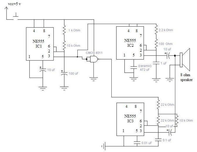
Two Tone Generator - This two-tone generator includes 3 ICs NE555 Astable Multivibrators. You can vary the
duration of each tone by changing the 10k resistor or 100MF capacitor at IC1 or changing resistors and capacitors
at IC1/2 for higher or lower tone. . . . [Designed by Andrew R. Morris]
Two Tone Generator - This two-tone generator includes 3 ICs NE555 Astable Multivibrators. You can vary the
duration of each tone by changing the 10k resistor or 100MF capacitor at IC1 or changing resistors and capacitors
at IC1/2 for higher or lower tone. . . . [Circuit Designed by Andrew R. Morris]
Two-tone doorbell using 555
timer - No circuit description, schematic only. . . [CdS
Electronic's website]
Universal Ding-Dong - One frequently finds gongs or chimes for sale in antique shops or Eastern markets. But
supposing one would want to wire these to a pushbutton at the front door to create a ding-dong doorbell? How
would this be done? Or consider, for a moment, more creative possibilities. How would one e. g. cause
wine-glasses or African drums to resonate when a doorbell is pressed? The circuit shown in Fig. 1 provides a
mechanical means of striking two gongs or chimes in sequence -- one when the doorbell is pressed, the other when
it is released. This it does by briefly activating two solenoids in. . . [Posted by Jospfh]
Wireless Doorbell - The transmitter circuit is made up of
two building blocks, the 303MHz RF oscillator and the 32kHz crystal controlled oscillator. The 303MHz oscillator
consists of a self-oscillating circuit made up of the coil. . . . [email Colin Mitchell: talking AT tpg.com.au]
<<<< Previous PAGE |