 |
|
|
|
|
 |
Wireless Battery Charger
By: Dave Johnson July 24, 2007 |
| |
|
Receiver Circuit Construction and
Testing |
| With the exciter circuit
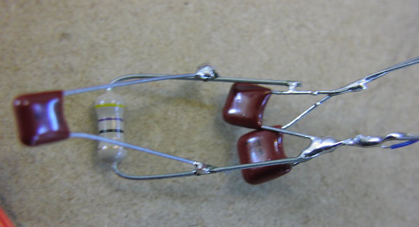
working, I then shifted my focus to the power collection coil. I again pounded nails
into a wood board. I spaced the four nails 1.75 inches by 3 inches. I wound 10
turns of 24 ga wire around the nail. When done, I measured the inductance at 20uH.
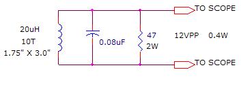
I then connected a 0.082uF capacitor across the coil and also installed a 47 ohm 1 watt
load resistor. I then connected the scope probe across the 20uH coil leads and
placed the coil at the center of the exciter coil. I connected two ends of a wire to
my signal generator and held the wire close to the coil while I varied the frequency.
The resonant peak was quite close to 125KHz. I reconnected my signal generator to the
driver circuit I fired up the exciter circuit. I adjusted the exciter frequency
slightly, for a peak across the receiver coil. I measured 12 volts peak to peak
across the 47 ohm resistor. This corresponded to 0.4 watts into the resistor. If I
moved the small coil, so its corner matched the corner of the exciter coil, the voltage
increased by 20% to about 15 volts peak to peak. That shifted the power to 0.6
watts. So, with the receiver coil in the center of the exciter coil, the +5v supply
measured 0.34 Amps (1.7 watts) while delivery 0.4 watts to the receiver coil. This
corresponded to an efficiency of about 24%. If I use a better FET driver circuit and
wind the exciter coil from 22 gage wire, I should be able to get fairly close to the 1
watt power transfer I was shooting for. I think with a few changes, the
overall efficiency might get closer to 50%. |
 |
|
 |
|
Power Receiver Network |
|
|
|
Next Step: The next step
would be to connect the receiver coil to a bridge rectifier circuit, with a filter
capacitor and a load resistor to see what kind of DC voltage I can produce.
Then I’ll figure out the best way to regulate the DC output to about 5v, to charge
the cell phone’s lithium ion battery. |
|
I might also consider ways to
manage the power to the exciter coil. With no receiver coil nearby, the Q of
the exciter turned network will be high and the average power will also be high.
Paradoxically, more power is drawn from the DC supply when there is no receiver coil
in the center of the exciter coil. I have a patent on a technique to detect a
nearby tuned network. Perhaps I could use a circuit similar to it to keep the
average power to the exciter circuit low, when there is no battery to be charged. |
|
|
|
|
|
| Issue #1,
Page 1,
, ,
Page 4,
Page 5 |
|