|
 |
DiscoverCircuits.com -- Hobby Corner
Last Updated on:
Tuesday, April 01, 2014 04:34 AM
Hobby Circuits'
Category List
The contents &
graphics of Discovercircuits.com are copyright protected.
LINKING to Dave's circuits is permitted but DO NOT COPY any files to your WEB
SITE server |
|
|
|
|
|
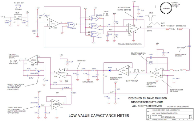
Precision Low Capacitance
Meter -- July 8, 2008
This circuit was originally designed to measure the volume of the fluid inside a 10cc
syringe. It used two copper foil strips attached to the outside barrel of the
syringe. The fluid between the two copper strips increases the capacitance. As the
fluid volume decreased, the capacitance also decreased. With the circuit shown
below, it is possible to calibrate the circuit, so the voltage produced is proportional
to the fluid volume inside the syringe.
With the values shown, the circuit produces a 5v DC
output, when the 10cc syringe is full. It is possible to measure the fluid volume to a
resolution of 0.01cc. The circuit can also be adjusted to produce a 5v DC output
voltage for a capacitance of 10 picofarads to a solution of 0.01 picofarads. |
| The circuit
measures the unknown capacitance by applying a clean 20KHz 5v peak to peak triangle
signal to the capacitor. The current routed through the capacitance is sent to a
current to voltage converter. The voltage that emerges is therefore a 20KHz square wave
signal, whose amplitude is proportional to the capacitance. The signal’s peak
amplitude is rectified and filtered to produce a DC voltage. Additional op amps provide
a means to adjust the zero and span of the circuit, so a fixed change of capacitance
will produce a known voltage change. A fixed 9v DC supply powers the complete
circuit. |
| |
|
Click on
Drawing Below to view PDF version of Schematic |
|
 |
|
|
|
|