|
Lapel microphone adaptor for PA systems - Simple adaptor features a balanceed output and lets you use electret lapel and headset microphones with PA systems. __ SiliconChip
Laptop Audio Amplifier - This circuit uses a power amplifier IC LA 4440 and two 6 watt speakers to amplify the audio output of a laptop. __ Electronics Projects for You
Latching Relay Bypass - Latching Relay Bypass Circuit __ Designed by Guitar Effect RC Keen
LED Meter PCB - Schematic Only __ Contact: info @ forsselltech . com
LED Musicolour: Light Up Your Music, Pt.1 - Now you can have a kaleidoscope of colour which continually changes in time to music. This consists of 16 strings of LEDs which are individually controlled by 16 frequency bands. Louder signals in each of those bands means that the respective LED string will be brighter. Use it for a Christmas light show, a disco or just for fun when playing music. __ SiliconChip
LED Musicolour: Light Up Your Music, Pt.2 - The new LED Musicolour makes building a spectacular light and music show easier than ever. In this second and final instalment, we explain how to build and test the unit and also detail how you can control it. __ SiliconChip
LF071 Mic Amplifier - A high quality microphone preamplifier using a single power supply, suitable for dynamic or electret microphones. The op-amp used can be any low noise, high performance type, e. g. NE5534, TL071, OPA 371 etc __ Designed by Andy Collison
Light Alarm with LDR - This musical light alarm circuit is very simple, uses only 7 components, a LDR and a 3.6 V battery or 3 x 1.2 volts rechargeable batteries. The well-known UM66 is used as the sound generator and will give a pleasent wake up alarm. As you probably know the LDR is a light dependent resistor. Normally the resistance of an LDR is __ Designed by Popescu Marian
Lil' Tiger AO-43 Organ to Guitar Amp Conversion - with reverb, pitch-shifting vibrato and tremolo __ Designed by G. Forrest Cook
Line level signal to microphone input adapter - Sometimes there is need to convert line level signals to such signal that it can be connected to microphone input. Because the line level signals are typically in range of 0.5.2V and the microphone signals are in millivolt range, quite much attenuation is needed to match the signal levels. This means that typically you will need 40-50 dB of attenuation __ Designed by Tomi Engdahl
Line Mixer - The circuit is an audio mixer circuit so simple as it can be. There are two dual logarithmic potentiometers in the circuit to adjust the input signal levels and some resistors to do the actual mixing. The circuit is totally passive, so no power supply is needed. The circuit is suitable __ Designed by Tomi Engdahl
Linear FM 30Watt - A amplifier of medium force RF for the FM, is always essential for the amateur that wants it strengthens some small transmitter, that likely it has already it manufactured! The present circuit can give force 25-30W, with control no bigger than 4-5 W. __ Contact: IQ Technologies
Line-In audio amplifier Part 1 - Welcome to Part 1-QRP WorkBench Line-in Audio Amplifier __ Contact: Vasily Ivanenko
Line-In audio amplifier Part 2 - Welcome to Part 2-QRP WorkBench Line-in Audio Amplifier __ Contact: Vasily Ivanenko
Linkwitz Cosine Burst Generator - Based on work done by Siegfried Linkwitz (reproduced with his permission) __ Designed by Rod Elliott ESP
Liquidator Tube Phaser/Chorus Effect - This project involves the conversion of a Hammond AO-47 organ vibrato unit into a 4 phase guitar/music phaser/chorus box. The individual phase signals can be mixed for a wide variety of sounds. The Liquidator name comes from the liquidy sounds that the device creates, it wiggles the audio all around. Used Hammond vibrato units can often be purchased for little money on eBay and provide the majority of the circuitry for this device. The Hammond AO-41 box can also be used for this project, it has a similar phaser circuit and one extra 7 pin tube socket. Here is the Original Hammond AO-47 Schematic for reference. __ Designed by G. Forrest Cook
Listen Amplifier - 1.5V and 3V schematics only. No circuit description at this time. __ Designed by Andrew R. Morris
Little Guitar Amp - I built this little guitar amp for my brother, Rich, a while back. Originally it was sort of a Fender "Champ" copy with a 12AX7 front end. I recently converted it to use a single EF86 pentode, instead. I like it much better this way. The amp chassis fits into a small maple open-back box with a single 10" speaker. Rich built the box __ Designed by Bob Danielak
LM317 Audio Amplifier - You probably know that LM317 IC is used as an adjustable voltage regulator, but did you know it can be used as an audio amplifier? This is a class A audio amplifier built with LM317 that delivers a maximum 1W audio power. Use a good heatsink for the LM317 IC and adjust the 5K variable resistor so that you have 4.5V on __ Designed by Popescu Marian
LM358 preamp - Another very simple audio preamp to build. all parts should be available at your very local electronics shop. __ Designed by Andy Wilson
LM380 2.5 watt Audio Amplifier - No circuit description, schematic only __ CdS Electronic
LM386 0,325W Audio Amplifier - The LM386 is a power amplifier designed for use in low voltage consumer applications. The gain is internally set to 20 to keep external part count low, but the addition of an external resistor and capacitor between pins 1 and 8 will increase the gain to any value from 20 to 200.
LM386 Audio Amplifier - Here is a simple audio amplifier circuit built around 8-pin integrated circuit LM386. The author’s prototype is shown in Fig.1. Circuit and working Circuit diagram of the LM386 audio amplifier is shown __ Electronics Projects for You
LM386 Audio Amplifier - This simple amplifier shows the LM386 in a high-gain configuration (A = 200). For a maximum gain of only 20, leave out the 10 uF connected from pin 1 to pin 8. Maximum gains between 20 and 200 may be realized by adding a selected resistor in series with the same 10 uF capacitor. The 10k potentiometer will give the amplifier a variable gain from zero up to that maximum. __ Contact: Charles Wenzel of Wenzel Associates, Inc.
LM3875 Gainclone Power Amplifier - This is a basic design with a single LM3875TF chip per side, and one shared toroidal transformer. I will be making two of these amplifiers simultaneously but with a few critical component differences. One is based on standard components, and one on premium components. There was a lot of
LM3876 GainClone Amplifier - The amp is based on the Project 19 PCB, so uses a pair of LM3876 (or LM3886) power opamps, run from a ±35V supply. I used a cut-down P88 preamp PCB because I only wanted one preamplifier stage, but the entire board can also be used. Alternatively, the P19 amp can be run at higher gain than normal, alleviating the need for a preamp at all. The down side of this is that the noise level will be higher, and background noise may be audible with efficient speakers and/ or very quiet surroundings.
LM3886 Amplifier - When I fired it up for the first time, I was immediately surprised with how much power was available, the level of detail and the nice bass response. It sounded much better than I was expecting and much better than it should considering the simplicity and low cost. Initially, I thought it sounded a little bright, but after about 12 hours the sound became more relaxed.
LM3886 Gainclone 2x68 Watt Full Amplifier - In this application, we are building a gaincard like amplifier. This application type is named gainclone in audio world. To take a satisfactory audio response, we are adding a Linkwitz equaliser to the feedback line and adding bass compensation also. We are using LM3886
LM3886 Monoblock Gainclone Amplifier - This is a monoblock Gainclone amp based on a LM3886 IC which is more suited to 4 ohm loads. It will output 70 Watts into 4 ohms. This version also uses a very high capacitance PSU and a snubber. The case is made entirely out of recycled aluminum bought from scrap metal yards.
LM3886 Power Amp with DIY Chassis - This is a simple chassis using just 4 aluminum panels and 2 heatsinks. Designed around dimensions to tightly pack in a LM3886 chip amp kit. The top and bottom panels sit in ridges cut into the heatsinks with a table saw, and then the front and back panels just bolt into the end fins. Rear panel fixings are held with M3 nut and bolts, and panels that join to the heatsinks are held by M4 bolts tapped directly into the heatsinks so no additional brackets are required. Heatsinks are 75 x 160 x 50mm with a 10mm thick base.
Loud Speaker Protection & Muting - Protect speakers from turn-on and turn-off transients and amplifier faults __ Designed by Rod Elliott ESP
Loudness Control - When listening to music at low volume levels, bass and treble frequencies are attenuated more than mid frequencies. This loudness control alters the frequency response curve to correspond roughly with the equal loudness characteristic of the ear. The circuit shown, is for a single channel, so for a stereo system, two such units should be built. This circuit has a boost of 13dB at 20Hz and approximately 9dB at 20kHz. __ Designed by Andy Collison
Loudspeaker Peak Indicator - Modern loudspeakers boxes are relatively insensitive to overdriving signals, however it is still important to limit the power driving it to avoid clipping of the audio signal. A broken sound from an overdriven loudspeaker is not only annoying to the the ears but also the loudspeaker itself can be damaged by the continous __ Designed by Popescu Marian
Loudspeaker Protection - Something you should use in any amplifier, especially in discrete amplifiers, is loudspeaker protection. The first part is the DC detector. This circuit will trigger the Off output if DC is present on the audio lines. The input goes through a low pass filter and then through the diodes. If there's any DC on the lines it will turn on the two transistors who will then turn on Q3, which triggers the Off signal.
Low Cost Mixer - A simple mixer circuit suitable for mixing microphones or effects outputs. The overall gain from input to output is one if the pot related towards the input is full up. You'll be able to generate this a net gain of ten (or any other reasonable gain) by lowering the input resistor towards the second op amp.10K in this position provides a gain of 10db, or 20db.
Low frequency / audio frequency DB output meter - Schematic only, no circuit description __ Designed by Guy Roels ON6MU
Low impedance microphone Amplifier - The circuit is a microphone amplifier for use with low impedance (~200 ohm) microphones. It will work with stabilized voltages between 6-30VDC. If you don't build the impedance adapter part with T1, you get a micamp for higher impedance microphones. __ Designed by Peter Jakab
Low Noise Balanced Microphone Preamp - A discrete front end makes this balanced microphone preamp very quiet __ Designed by Rod Elliott ESP
Low Noise Microphone PreAmplifier - This is a design for a low noise microphone preamplifier, which is ideally suited to low impedance (600 Ohm nominal) microphones. One limitation is that it is not balanced, which is not a problem in a home recording environment, but will allow the mic lead (and case) to pick up noise with long cable runs or in a hostile environment. __ Designed by Rod Elliott ESP
Low Pass Filter for FM 88-108 MHz - Filter used for eliminate unwanted harmonic frequency at second and third. Notch filter, Band Pass Filter (BPF) , and High Pass Filter (HPF) sometime combined in constructing LPF design. Schematic below for FM Broadcast Lowpass Filter 88-108 MHz
Low pass filter for subwoofer - The acoustic spectrum is extended by very low frequencies 20Iz and reaches as the 20000Iz in high frequencies. In the low frequencies is degraded the sense of direction. This reason us leads to the utilization speaker for the attribution of very low frequencies. The manufacture that to you we propose distinguishes these frequencies, in order to him we lead to the corresponding amplifier. The acoustic filters are met in various points in the sound systems.
Low Pass Filter, 3Khz, with an Audio Amp - This circuit uses a switched capacitor filter IC from National Semiconductor to filter signals with frequencies higher than the 3KHz needed for voice audio. The schematic includes an audio amplifier that is designed to drive a standard audio head phone . . . Hobby Circuit designed by Dave Johnson P.E.-June, 2000
Low pass filter-subwoofer filter - The acoustic spectrum is extended by very low frequencies 20Iz and reaches as the 20000Iz in high frequencies. In the low frequencies is degraded the sense of direction. This reason us leads to the utilization speaker for the attribution of very low frequencies. The manufacture that to you we propose distinguishes these frequencies, in order to him we lead to the corresponding amplifier. The acoustic filters are met in various points in the sound systems. __ Designed by Steve Filianos
Low Power Audio Amplifier Based on LM386 - Another super-simple circuit. You could use this circuit to drive a low power speaker from a sound effects module or a noise generator. Or you could build your own amplified speakers for use with your computer. __ Designed by Bill's Electronics Reference Library
Low power audio Amplifier using BC109C along with BD679 & BD680 Darlington pairs - As can be seen from the circuit diagram we are really using five transistors as the BD679 and BD680 are "Darlington" pairs of transistors. The led must be a green led for correct operation. (The voltage across a green led is higher than the voltage across a red led.) When using a 12v supply the voltage at T1 collector should be (about) 5v and at T2 base (about) 7v. This amplifier will be unstable (it will oscillate) without the 4k7 variable resistor connected to the input. __ Designed by © David Hoult
Low Power Op-Amp-Audio Amp Intercom - The example below illustrates using an op-amp as an audio amplifier for a simple intercom. A small 8 ohm speaker is used as a microphone which is coupled to the op-amp input through a 0.1uF capacitor. The speaker is sensitive to low frequencies and the small value capacitor serves to attenuate the lower tones and produce a better overall response. You can experiment with different value capacitors to improve the response for various speakers. The op-amp voltage gain is determined by the ratio of the feedback resistor to the series input resistor which is around one thousand in this case __ Designed by Bill Bowden
Low Power Single-Ended 6SN7 Amp - I built this little amp for my computer at work. It sounds pretty darn good thru some old speakers from an Emerson tube console. At <1/2 Watt it is STILL too loud for my office. __ Designed by Bob Danielak
Low Power Single-Ended 6SN7 Amp power supply - This is the power supply for the 6SN7 Amp __ Designed by Bob Danielak
Low Voltage Audio Amplifier - This experimental (3) transistor class A audio power amplifier delivers 25mW into an 8Ω load, or 50mW into a 4Ω load using only a 1.5V power source. At such low voltages, there are many issues to consider and much to learn. To the best of my knowledge the following information is new to the world. Background Months __ Designed by Jim Keith
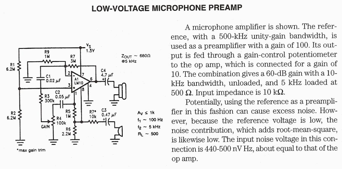
Low Voltage Microphone Preamplifier - This is a low voltage microphone preamplifier circuit with a 1.5V power supply. The reference, with a 500 kHz unity-gain bandwidth, is used as a preamplifier with a gain of 100. Its output is fed through a gain-control potentiometer to the op amp, which is connected for a gain of 10. The combination gives a 60 dB gain with a __ Designed by Popescu Marian
Low voltage microphone preamplifier using LM10 - Circuit Only
Low Voltage PreAmplifier - A low voltage preamplifier optimized for 3 Volt operation. __ Designed by Andy Collison
Low-cost audio filter suppresses noise & hum - 03/02/06 EDN-Design Ideas Passive filter requires no dc powerThe low-cost composite passive filter in this Design Idea requires no dc power and can enhance the performance of audio equipment and instrumentation by rejecting power-supply hum and spurious pickup from AM, FM, and low-band VHF transmissions (Figure 1). The composite filter comprises a cascade of three simple filters: a T-section highpass filter to reject power-source hum and two π-section lowpass filters to reject spurious RF signals. As a starting point, the three filter sections present a lossless 0.01-dB Chebyshev response at a 50Ω impedance level, but you can scale the components' values to meet other impedance requirements. Design by Richard Kurzrok
Low-Cost Audio VCA Has High Performance - 01/19/95 EDN-Design Ideas The inherent matching between the two transconductance amplifiers in IC1(Fig 1]facilitates a voltage-controlled amplifier(VCA]that offers high performance and low cost. The circuit's maximum input voltage is +20 dBu(dBu=dB referred to 775 mV rms]. THD measures less than0.015%; noise, -70 dBu; and control-voltage feedthrough, -70 dB Design by Mike Sims, Lectrosonics Inc, Rio Rancho, NM
Low-Cost Incorporates Mixing & Amplifying Functions - 10-Jul-08 EDN-Design Ideas Using an amplifier with a power-down disable, you can combine the mixer and the amplifier functions Design by Guus Colman, Guy Torfs, Johan Bauwelinck, and Jan Vandewege, INTEC/IMEC, Ghent University, Ghent, Belgium
Low-cost Transistorised Intercom - The circuit described here uses three easily available transistors only. Even a beginner can easily assemble it on a piece of veroboard. The circuit comprises a 3-stage resistor- capacitor coupled amplifier. When ring button S2 is pressed, the amplifier circuit formed around transistors T1 and T2 gets converted into an asymmetrical astable multivib-rator generating ring signals. These ring signals are amplified by transistor T3 to drive the speaker of earpiece.
Magentic phono cartridge phono preamp - Gotta stack of 'old' vinyl LPs sitting around that you'd like to play through your computer sound card or record to your new CDR-W but don't have a stereo pre-amp to do it? Then build this magnetic pre-amp with RIAA curve play back (equalization) . Make sure to use shielded wire for all your connections as well as a 9 volts battery to eliminate any AC(Hum) noise. This is a very sensitive amplifier and will output up to 350mv at 1khz for 5mv input from a magnetic cartridge. __ Designed by © Laurier Gendron, Burnaby, B.C., Canada
Magnetic cartridge Amplifier - Schematic Only __ Designed by Andy Wilson
Marshall 100W Super Lead adapted for use as a distortion stompbox. Schematic & PCB layout. - The Thunderchief project, released in March 2004, was the first runoffgroove.com circuit that was developed using the tubes-to-FETs process. Enlightened and inspired by Doug Hammond's excellent Meteor circuit, we used the same approach in an effort to capture some of the legendary magic of the Marshall Super Lead. The circuit's performance pleased us, but there were issues. __ Contact: holler @ runoffgroove.Com
Marshall 18W adapted for use as a distortion stompbox - The Marshall 18W adapted for use as a distortion stompbox. __ Contact: holler @ runoffgroove.Com
Marshall Professional MKII Guitar Fuzz - This is probably one of the most legendary fuzz pedals that has ever existed, and for good reason too!This thing can produce some completely saturated fuzz that is capable of slipping into feedback easily if you crank it up loud enough. I just can't
Matchless DC/30 adapted for use as a distortion stompbox - Back in the mid-90s, the Matchless DC/30 became one of the first boutique amps to hit the market. It excelled at clean tones, as well as thick Vox-like overdriven lead sounds. There is good reason for the similarity in sound to a Vox amp. The lead channel of the DC/30 appears to be a modified Vox AC30/4. The AC30/4 amp featured the EF86 pentode preamp tube, just as the Matchless design. __ Contact: holler @ runoffgroove.Com
May Queen - A stone cold crazy treble-boosted overdrive. __ Contact: holler @ runoffgroove.Com
Melody generator for greeting cards - his tiny circuit comprising of a single 3 terminal IC UM66 can be built small enough to be placed inside a greeting card and operated off a single 3V flat button cell.
There is not much to the circuit. The UM66 is connected to its suppl. __ Designed by Radioland.nt.au
Metronome - A Universal Power supply based on the L200 regulator, which includes an outboard pass transistor to boost output currents up to 4 amps. __ Designed by Andy Collison
Metronome & Pitch Generator - CMOS
IC1 and IC2B quad AND gate form a 2.4576 MHz crystal oscillator plus a 2400 times divider. IC3A provides further division by 16, delivering a 64 Hz stable frequency square wave. This frequency is multiplied (by means of Phase Locked Loop IC5, double decade divider IC4 and IC3B 4 bit binary divider) by the number set by three miniature BCD thumbwheel switches SW1, SW2 and SW3: units, tens and hundreds respectively. __ Contact: Flavio Dellepiane, fladello @ tin.it
Mic Audio Mixer - The following design is the circuit diagram of microphone audio mixer with 3 input channels. It use 741 op-amp to amplify the input signal. This circuit can be used for dynamic microphone. __ Designed by Aaron Cake |