|
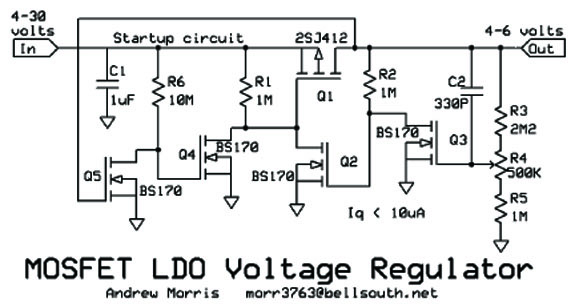
This circuit has excellent voltage
regulation, due to positive feedback through R2 however the circuit must be started up.
This is done by Q4 and Q5. If the circuit does not need to be started under load,
Q4, Q5, and R6 can be deleted. You must then place a 1 meg resistor between the
source and drain of Q1. C2 slightly speeds response to rapid load changes and can be
changed in value or deleted.
Due to the extremely high impedances to this
circuits, it would oscillate with capacitive loads on a protoboard, but with stable when
built up on a small piece of perfboard. The circuit draws an overhead current of
less than 10uA. Drop-out voltage approaches zero. It is entirely dependent on
the load and the Rds of Q1. The only shortcoming of the circuit is that the set
voltage will vary from one Q3 part to another. Each copy of the circuit would have
to be adjusted. |