|
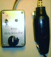
This circuits regulates the speed of a small
drill motor I use for PC board work. It is much handier for delicate work that a
large AD powered tool. The tool that I have came with a useless 9 volt AC adapter.
The motor would whine at high RMPs unloaded, but would slow to a crawl when loaded.
This circuits solved the problem.
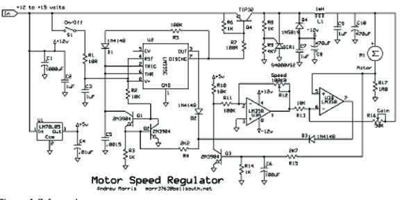
Q1, Q2 and U2 form a variable-frequency
pulse width modulator, controlled by U3. Q4 forms part of a step0down power
converter. Speed regulation is accomplished by sensing the motor current with R17
and using it as positive feedback to compensate for motor resistance loss. The gain
pot should be set to a point just below the point where the motor speed oscillates.
After finding this point, you may want to change the value of R11 to get better speed
control range.
Q3 limits motor current. D4 and C8
capture some of L1s inductive kick to produce a loosely regulated -12 volts for U3.
SCR1 acts like the usual flyback diode one c8 has stored the needed energy, preventing
significant power losses. |