|
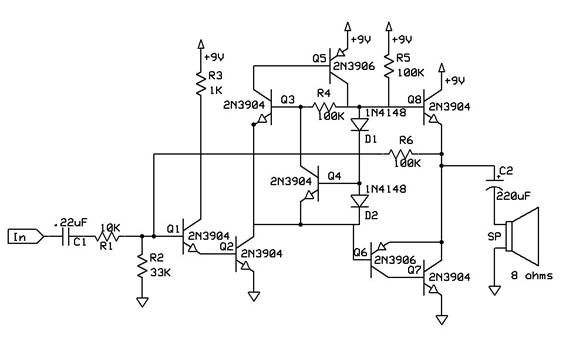
This circuit is best used in a non-high
fidelity application (i.e. speech audio) where battery life is critical. This is an audio
power amplifier, similar to what is common in transistor radios and other portable audio
equipment. This circuit however, has an ultra-low quiescent current of about 300uA, due to
a unique bias circuit. I don’t even know of a chip that does that. This circuit also has
much higher open-loop gain, due to the bootstrap effect that the circuit provides as a
by-product of its operation.
Diodes D1 and D2 perform the usual task
of closing the gap between the point where Q7 or Q8 stops conducting and where the other
transistor starts conducting. This gap causes an effect known as “crossover distortion”.
To prevent crossover distortion, Q5 and Q6 would normally be slightly in simultaneous
conduction when no signal is present, wasting precious battery power. Because precise
control of the quiescent current is extremely difficult, it is always adjusted such that
significant power is wasted. This circuit uses an extremely tight control loop to maintain
the proper voltage across D1 and D2 virtually eliminating crossover distortion with almost
no simultaneous conduction of Q7 and Q8. I say “virtually”, because under heavy load, a
tiny amount of crossover distortion can just be seen on the scope, but would be completely
inaudible.
Q3 and Q5 form a regenerative (infinite
gain) amplifier, similar to an SCR. It would indeed latch up like an SCR without negative
feedback from Q4, which senses the voltage across D2. D1, having essentially the same
current, will have essentially the same voltage across it. R5 provides the start-up
current for Q3, which causes Q5 to conduct. This in turn, causes Q3 to conduct more,
causing Q5 to conduct more, producing the previously mentioned regenerative effect.
The voltage across D2 will keep Q4 just
barely in conduction. Since the diodes and transistors are all silicon, the voltage across
D1 and D2 will also be just exactly the voltage necessary to keep Q6 and Q8 just barely in
conduction. No wasted power. Note that D1, D2, Q4, Q6 and Q8 must be in the same
temperature environment. For larger amplifiers, they should be on the same heat sink. In
really big amplifiers, D1 and D2 should be replaced with 1N400x types. The quiescent
current will be proportionately larger.
If you want more quiescent current, or
need emitter current limiting resistors, you will have to add a resistor in series with D1
to get the added voltage. The drop across the resistor will be constant because the diode
current will be constant. Due to the infinite gain of the Q2 and Q4 combination, quiescent
current is essentially unaffected by battery voltage. Note that the circuit works poorly
if the diodes are replaced with resistors. The circuit works because the non-linearity of
the diodes matches that of the transistors’ E-B junctions.
An interesting by-product of this
process is the bootstrap effect it causes in the amplifier.
When Q2 conducts less, the current
through D2 conducts less as well. The control circuit increases the current through D2,
but feeds Q8 as well. On the positive half-cycle of the audio, the load impedance on the
collector of Q2 is extremely high, raising its gain considerably.
There is a trade-off here that one
should be aware of. This circuit produces another form of inaudible distortion.
Because the load impedance on Q2 is so much higher on the positive half-cycle, and the
regenerative amplifier (Q3 and Q5) feeds Q8, heavy loads on the amplifier will cause
slight rounding of the negative peaks. Slightly lower gain under load would be normal in
any amplifier of this type, but in this circuit, the positive peak doesn’t buckle as well
as the negative peak, like in a more conventional design.
Also, the circuit can be simplified,
depending on how much distortion you can tolerate in your application. Q7 can be deleted
if a 32 ohm load is used. With a 32 ohm load, and Q7 present, no crossover distortion is
visible, but only slightly visible with Q7 deleted. Also, Q1 can be eliminated, if a
little more rounding of the negative peaks is tolerable. This is also barely detectable
with a 32 ohm load. Lowering the gain will also lower any distortion the circuit
produces. The gain is determined by the ratio of R6 to R1 (10 in this case). R2 works with
R6 to set the DC operating point (voltage on the emitter of Q8).
I used this circuit in a telephone
headset amplifier without Q7 and it sounds just fine, but the whole system uses only 300uA
from a 9-volt battery without audio passing through it. It has had the same battery in it
(that was not new when I put it in) for about a year and it is still going strong.
The headset amp shuts off (to about 3uA consumption) after 2 minutes of inactivity. |