|
Circuits designed by David Johnson,
P.E.
Last Updated on:
Monday, December 25, 2017 02:08 PM
Master Category List - Dave's Circuits
The contents &
graphics of Discovercircuits.com are copyright protected.
LINKING to Dave's circuits is permitted but DO NOT COPY any files to your WEB
SITE server |
 |
|
|
|
|
|
More
PWM
Computer Controlled
PWM Circuit
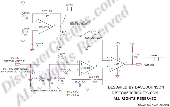
There are times when you wish to control a pulse
width modulation (PWM) signal with a DC voltage, ranging from 0v to 5v. This
voltage is often created by a computer interface. The circuit below performs
this voltage to PWM conversion. PWM signals are often used to control the speed of
DC motors and can also be used to control LED lamp light intensity. |
|
Two ICs are used for this converter. A dual op Amp generates a 20KHz square wave
signal. A triangle shape waveform is produced as part of that generator. That
signal is fed to the non-inverting side of a LM393 voltage comparator. The 0v to
5v control input is level shifted and attenuated to match the triangle wave peak to
peak voltage. That DC voltage is fed to the inverting side of the LM393
comparator. The comparator output is thus a TTL level signal, whose pulse width
can be controlled by the input DC voltage. With a 0v input, the duty cycle of the PWM
waveform is 0%. With a voltage of +5v, the duty cycle shifts to 100%. With the
component values selected, the PWM frequency is 20KHz but can easily be changed by
changing the resistor value at the R4 position. |
|
|
Click on Drawing Below to view PDF version of Schematic |
|
 |
|
|
|