|
 |
Circuits designed by David Johnson,
P.E.
Last Updated on:
Saturday, December 30, 2017 02:17 PM
List of Dave's Circuit Designs
The contents & graphics of
Discovercircuits.com are copyright protected.
LINKING to Dave's circuits is permitted but DO NOT COPY any files to your WEB SITE
server |
|
|
|
|
More Lithium
Battery Chargers |
|
Battery Amp-hour
Capacity Tester
Lithium Battery Charger 4 |
|
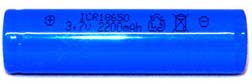
I bought some lithium ion
rechargeable batteries a while back. I was planning on using them to modify some solar
powered LED spot lights. What I like about these new batteries is that they are
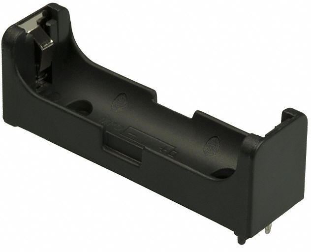
the same size as a standard 1.5v alkaline AA cell. With such a package, I can
use a standard AA battery holder. The battery manufacturer claims an Amp-hour
capacity of 2.2 Amp-hours. Usually, these Amp-hour figures are made using rather
small loads, conducted over a long period of time. If I’m going to use these
things for some solar powered pathway spot lights, I need to know what operating time
to expect. How long would these cells last if I pull about 20ma from them?
What voltage should I use to terminate the test? |
|
|
 |
 |
|
Lithium Ion Battery |
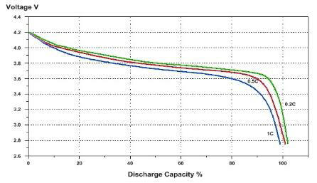
Lithium Ion Current Capacity Vs Voltage |
|
|
 |
 |
| AA
Battery Holder |
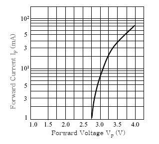
White LED Voltage Vs Current |
|
|
 |
|
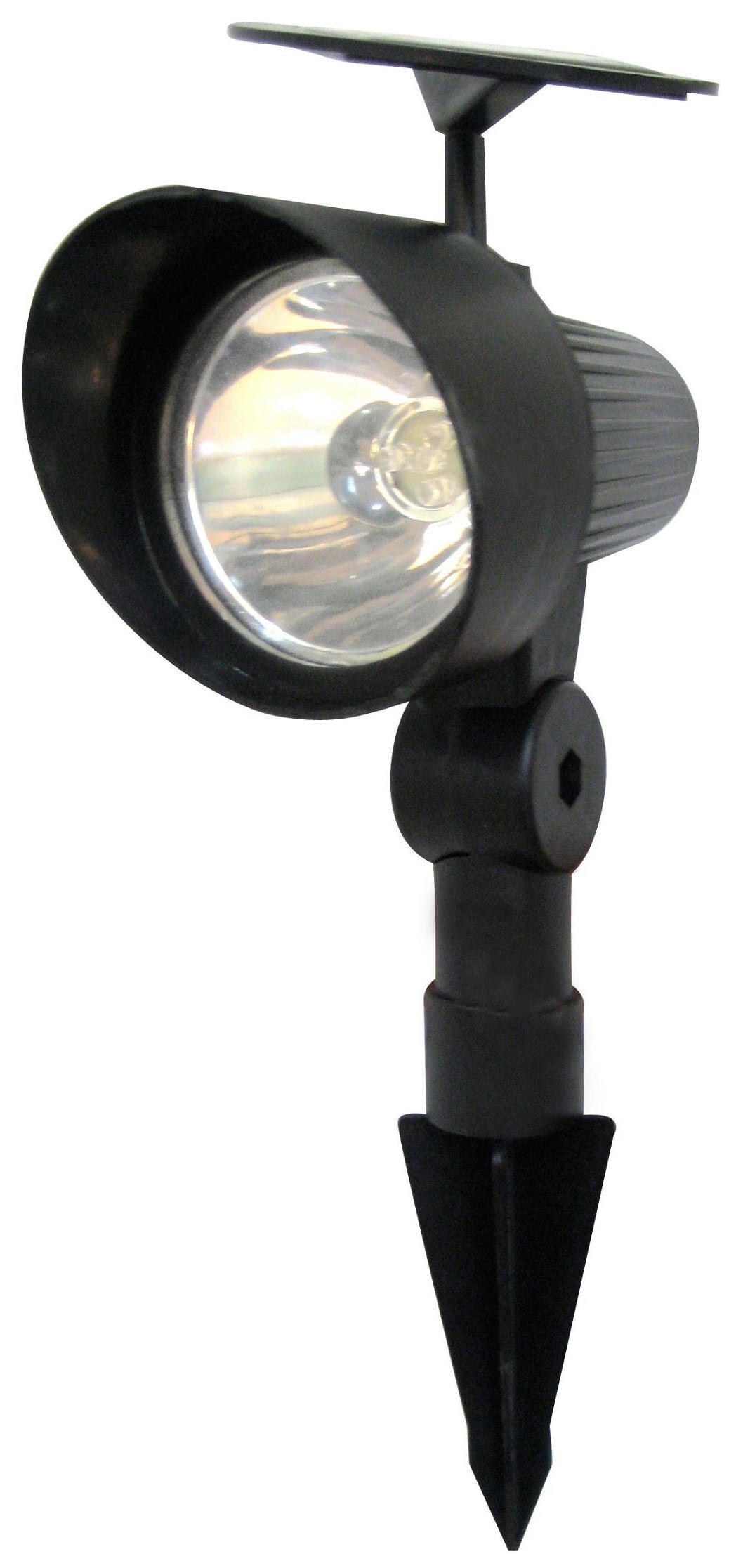
Solar Powered Spotlight |
|
| Based on
the battery curves shown, it looks like a good voltage to terminate a
discharge test would be at about 3 volts. Also, as shown by the typical
white LED forward voltage Vs current curve, it looks like when the LED reaches
3 volts, the forward LED current would be well below 10ma. That means
the light emitted by the LED would be about half as much as the 20ma figure.
That seems like a good target. So, the two curves converge nicely. |
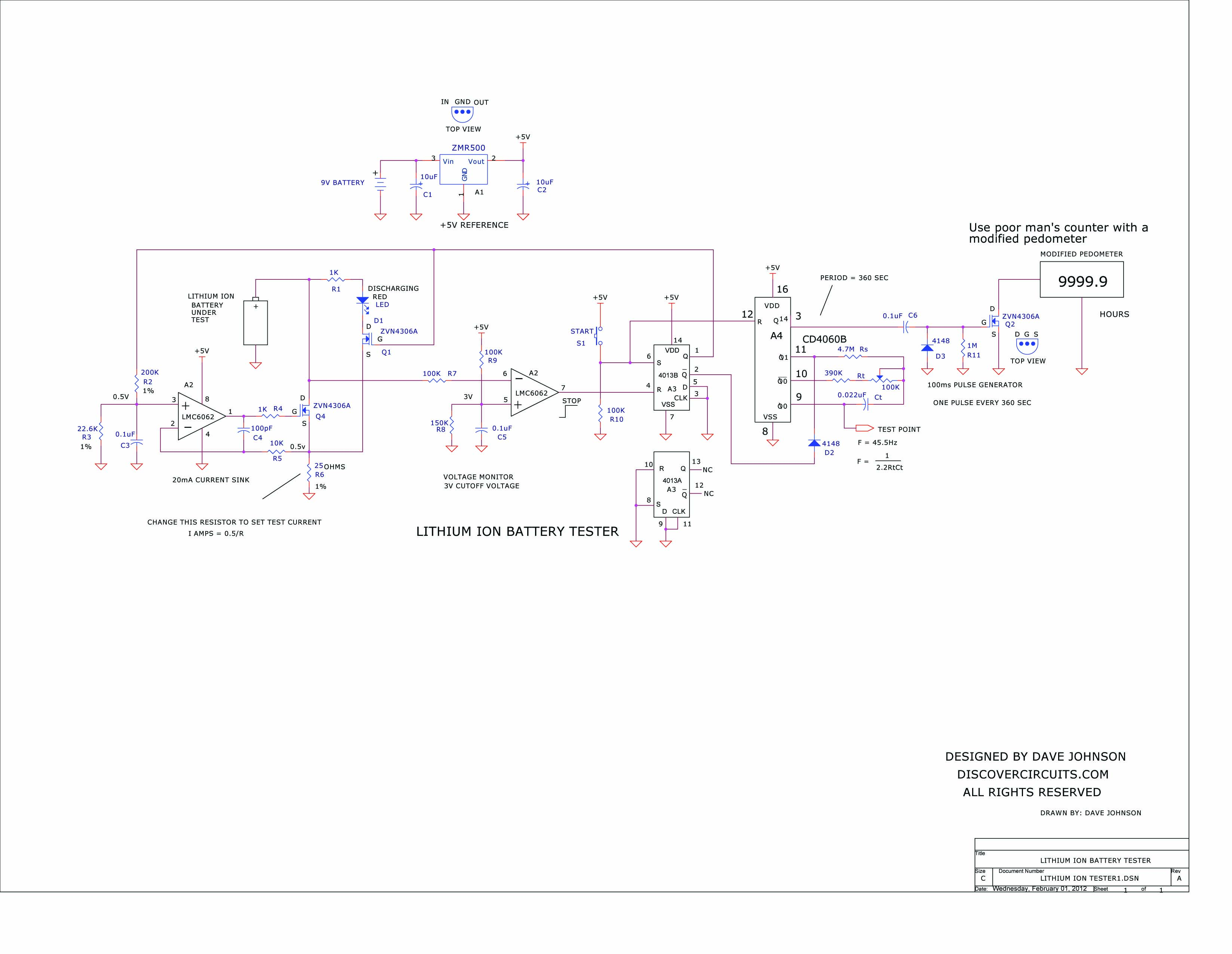
| I wanted a
way to test these and other batteries using an automated method. I want
to be able to start a test, then walk away and come back later to see the
results. The circuit I came up with is shown below. A 9v battery
powers the whole system. A dual op Amp is used to control the current
drawn from the battery under test and to also monitor the battery voltage.
A low power +5v regulator is used as a voltage reference and a power supply
for the logic devices. A CD4013 dual flip/flop is used as a set-reset
latch. A pushbutton switch is used to start the test, which latches the
flip/flop. When the battery voltage drops below 3.0v, the test is halted
and the flip/flop latch is reset. CD4060 is configured as 0.00277Hz
clock. The CD4060 has an oscillator and a 14 stage counter. With
the component values shown, the frequency is adjusted to 45.5Hz. By the
time this master clock works its way through the 14 stage binary counter, the
square wave signal which emerges has a period of one pulse every 360 seconds.
The output of the counter is connected to a pulse generator which shapes the
leading edge of the low frequency clock signal into a single 100ms pulse.
|
|
|
|
That pulse is connected to an n-channel MOSFET as a switch. The
transistor is connected to a modified pedometer, which counts the pulses and displays the
total number of pulses. With everything running right, the modified pedometer
displays hours and tenths of hours for the battery discharge test. If the lithium
battery has anything like a 2 Amp-hour capacity, the total discharge time with a 20ma load
should be about 100 hours. Such a battery would make an excellent power source for a
solar powered spot light. |
|
|
Link to Poor Man’s Pedometer:
../H-Corner/poor-man-pedometer.htm |
|
|
Click
on Drawing Below to view PDF version of Schematic |
|
 |
|
|
|
|