|
 |
Circuits designed by David Johnson, P.E.
Last Updated on:
Monday, December 25, 2017 02:06 PM
List of Dave's Circuit Designs
The contents & graphics
of Discovercircuits.com are copyright protected.
LINKING to Dave's circuits is permitted but DO NOT COPY any files to your WEB
SITE server |
|
|
|
|
|
More
Alarm Circuits; Safety
Circuits |
|
AC Power
Loss Alarm July 12, 2012 |
|
I’ve been
having a problem with my instant hot water system lately. This system circulates
electrically heated water throughout my house using a small pump. The pump is
wired into a ground fault interrupter (GFI) module. Every now and then, the GFI
trips, leaving me without hot water. What I need is an alarm to tell me when AC
power on that outlet has been turned off by the GFI. I figured a 9v battery
powered loud chirping beeper would be the ticket for this kind of alarm. The chirping
sound would draw my attention and let me know that I need to reset the GFI switch,
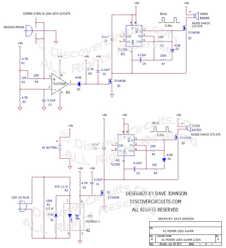
without waking the whole neighborhood. My circuit is shown below. |
|
|
| I had a choice between two different
ways to detect when AC power was turned off at the GFI outlet. One method used
a small opto-isolator, a diode and a resistor, which is connected directly to the
two power prongs on the GFI output. This method brought 120vac into the box.
This circuit would be foolproof but would decrease the overall safety of the alarm
box. Another method was a bit unorthodox. It sensed the electric field
emitted by the active prongs on the outlet, using a pair of copper strips inside the
box. I still used the 3rd ground prong on the outlet as a means to hold the
box onto the outlet, putting the copper strips into predictable positions over the
sockets. Two copper strips are used so the box could be plugged into either the
upper or lower socket. In case people had problems with the non-contact
method, I show both sensing methods in the schematic below. The alarm housing
I suggest is a small plastic box, which has a convenient 9v battery compartment,
available from Digikey. |
 |
 |
|
GFI Outlet |
Alarm Plastic Box |
|
| The circuit is powered by a 9v
battery and is packaged in small plastic box with a 9v battery compartment.
A very popular opto-isolator is used to monitor the power line. As long
as there is AC power to the input, the n-channel FET Q1 is kept turned off.
As soon as power is lost, +9v is switched to the beeper circuit. I used
a CMOS
version of the 555 timer to produce a 50ms pulse every 3 seconds.
The output of the timer drives an n-channel FET which in turn drives a very
loud siren type beeper, available from Radio Shack. The result is a
sound maker which is very loud but only produces short chirps. The sound
is loud enough to be easily heard without drawing a lot of average current
from the 9v battery. Using the short 50ms pulses every 3 seconds, the
average current when beeping is reduced to about 2 milliamps. In standby
mode the current is about 2 microamps. |
 |
| The electric field method uses
many of the same parts but uses a low power voltage comparator to sense the AC
field from the active power outlet. When power is lost, the unit starts
beeping. |
Piezo Siren
from Radio Shack |
|
| |
|
|
Click
on Drawing Below to view PDF version of Schematic |
|
 |
|
|
|
More
Alarm Circuits; Safety Circuits
List of Dave's Circuits
Dave's Circuits with Descriptions
Dave's Circuits by Category
eMail David A.
Johnson, P.E. about this circuit |
|
|