|
 |
Circuits designed by David Johnson, P.E.
Last Updated on:
Saturday, December 23, 2017 03:21 PM
List of Dave's Circuit Designs
The contents & graphics
of Discovercircuits.com are copyright protected.
LINKING to Dave's circuits is permitted but DO NOT COPY any files to your WEB
SITE server |
|
|
|
|
More
Indicator |
|
DC Current Indicator 6 -- February
7, 2009
|
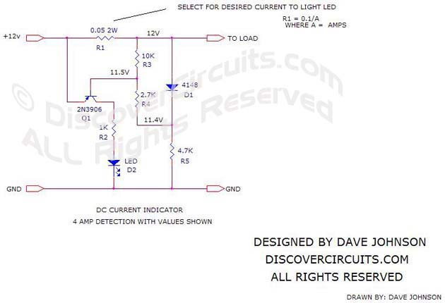
| The circuit below is a simple way to
indicate when DC current is flowing through a wire. The circuit is designed so
it will turn on a LED indicator light, whenever the voltage drop across a shunt
resistor exceeds about 0.1 volts. The value of the resistor can be selected
based on the desired current flow. Although I show a circuit for 12v operation, the
circuit can be used over a wide range from 3v to perhaps 24v. |
|
|
| A single NPN
transistor detects the voltage drop across the shunt resistor. A silicon diode is used to
bias the transistor base terminal at about 0.5v below the supply voltage. With such a bias
voltage, only an additional 100mv voltage drop is needed to start turning on the
transistor. Since both the transistor and the diode are nearly at the same
temperature, their voltage drop with temperature should track. The circuit should
therefore operate over a fairly wide temperature range. |
| Don’t expect
precision from this circuit. With marginal current, the LED may only turn on partly.
The component values shown are set for a 4 Amp indication, but the LED may actually start
turning on with only 3 Amps. |
| Select the shunt
resistor size as needed. As an example, if you want to detect a current flow of 50
Amps, the shunt resistor should be about 0.002 ohms and should be able to dissipate 5
watts. |
|
|
Click
on Drawing Below to view PDF version of Schematic |
|
 |
|
|
|
|