|
DiscoverCircuits.com -- Hobby Corner
Last Updated on:
Tuesday, June 01, 2021 03:06 PM
Hobby Circuits List
The contents &
graphics of Discovercircuits.com are copyright protected.
LINK to Dave's circuit, but DO NOT COPY any files to your WEB
SITE server |
 |
|
|
|
|
|
|
More
RFID Circuits |
|
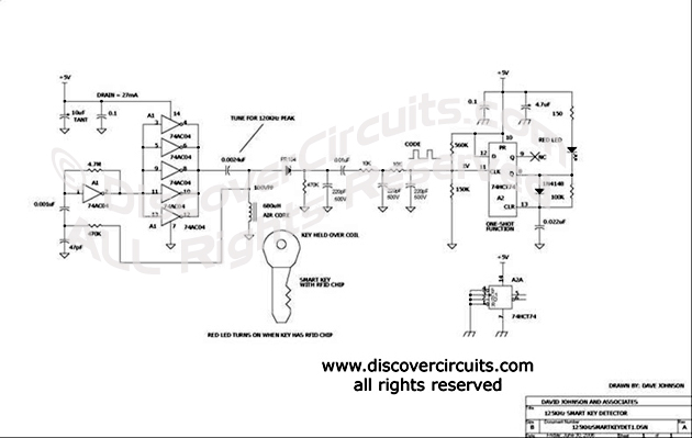
Wireless RFID Smart Key Detector
Circuit
designed
by David Johnson, P.E. |
| The hobby circuit below
was designed
to indicate if a key held over the small coil of wire contains a 125KHz
RFID chip. These chips are often used in smart car ignition keys. The left
side circuit forms a 125KHz power oscillator, which drives the 680uH air core
inductor. |
|
|
The magnetic field generated excites the RFID chip
inside the key. The AM signal produced by the key is stripped off of the
125KHz carrier, is filtered and is routed to the clock input of a flip/flop. The
flip/flop is configured as a one-shot pulse generator. With the component
values shown, the clock signal only has to be about 100 millivolts peak to peak to
toggle the one-shot action. If the flip/flop is toggled, a red LED is turned
on. Try about 250 turns of 30 gage magnet wire with a diameter of one inch for the
air core coil. Tune the electronic circuit for 125KHz by adjusting the value
of the series 0.002uF cap.
|
|
|
|
|
Click on Circuit Below to view PDF of Schematic |
|
 |
|
|
|
More
RFID Circuits
Hobby Circuits List
eMail David A.
Johnson, P.E. about this circuit |