|
DiscoverCircuits.com -- Hobby Corner
Last Updated on:
Tuesday, June 01, 2021 03:06 PM
Hobby Circuits List
The contents &
graphics of Discovercircuits.com are copyright protected.
LINK to Dave's circuit, but DO NOT COPY any files to your WEB
SITE server |
 |
|
|
|
|
|
|
More
Light Detector Circuits |
|
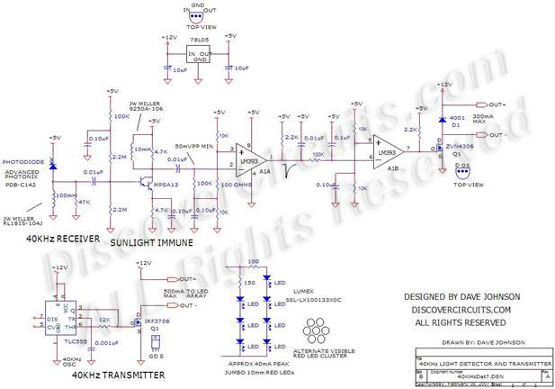
40KHz Light Detector with
Sunlight Immunity
designed
by David A. Johnson, P.E. |
| This hobby circuit below
was designed
to turn on an external 12v relay, whenever it detects light from a
nearby LED light source, modulated at 40KHz to 50KHz. This circuit was
originally designed
to operate from a fast moving vehicle. The light transmitter was
positioned at a stationary position, while the matching receiver was mounted on the
vehicle. This hobby circuit has high ambient light immunity and in most cases,
can operate in direct sunlight. |
|
| An
array of about 30+ infrared LEDs, powered from a +12v source, is used as the source of
40KHz modulated light. An alternate light source, made from an array of 7 visible red
LEDs housed in a 10mm �jumbo� package, is also shown in the schematic below. A simple
555 timer, wired as a 40KHz oscillator and connected to an n-channel FET, drives the
LEDs, powered from a +12v DC source. |
|
A small inexpensive photo diode, housed in a clear
plastic package, similar to a 5mm LED, is used as the light detector. It is reversed
biased with a +5v supply and connected directly to a 100mH coil. The photo diode
leaks current into the inductor at a level which is directly proportional to the
light intensity. The inductive load provides an efficient way to separate the weak
AC current signal generated by the modulated light source from the strong ambient
light current, which includes direct sunlight. The voltage that appears across the
inductor is a combination of AC and DC components. The resistance of the coil means
a DC voltage will appear across the coil equal to the leakage current times the coil
resistance. |
|
|
|
But, the
reactance of the inductor forms a much higher load impedance to any AC component from
the photo diode. At 50KHz, the reactance is equal to about 30K. Using a capacitor, the
DC signal across the inductor is blocked, allowing the AC signal to pass. The AC signal
is fed to a transistor Amplifier, which uses a NPN Darlington device. A smaller 10mH
inductor forms the load impedance of the Amplifier and insures that only signals lefted
at about 40KHz will be Amplified. The transistor Amplifier provides a voltage gain of
about ten.
The output of the Amplifier is fed to the input of a
voltage comparator circuit. With the component values show, the comparator will produce
a logic level output when the 40KHz from the Amplifier reaches about 50mv peak to peak
or greater. The output of the first comparator is fed through a filter network, which
will generate a negative voltage swing, whenever a 40KHz signal is detected. The second
filter network requires multiple comparator transitions before the DC voltage swings low
enough to toggle the second comparator. The second voltage comparator, within the dual
comparator package, is used to produce a positive logic swing, when several cycles of
40KHz signal is detected. The output of the second comparator is connected to a power
FET, which drives the external relay. |
| I
have been asked many times if we can predict the signal level at the light detector end.
The answer is yes, we can. The typical half angle light emission pattern from these LEDs
is about 15 degrees. At a distance of 30 feet, the light will form a circular pattern
about 15 feet in diameter. This comes from the equation D = (2)(S)(tanL), where D is the
diameter of the light pattern,
is the distance from the LED light source and detector
and L is the divergence half angle of the LEDs. Assuming about 10 milliwatts of light
from each LED, the total light power launched from the 30 LED array would be about 0.3
watts. The area of illumination at 30 feet would then be about 200 square feet or about
30,000 square inches. The light detector area is about 0.030 square inches. Therefore,
of the 0.3 watts of infrared light launched, only about 0.3 microwatts will be collected
by the photo diode. With a conversion factor of about 0.5 milliamps of photo diode
current per milliwatt of 880nm light, the photo diode current will be about 150
nanoamps. The reactance of a 100mH coil at 40KHz is about 25K. So, the expected peak to
peak signal induced across the coil from the 150 nanoamps of current from the photo
diode will be bout 7mv peak to peak. This is a bit on the small side for a direct
conversion method, so an Amplifier was needed. With a gain of about X10, the 7mv peak to
peak signal across the coil will be turned into a 70mv peak to the input of the
comparator circuit, which is enough to toggle the circuit. |
|
When using the
7 10mm jumbo LEDs, the light pattern is a bit tighter. Each device has a half
angle of about 5 degrees. This yields an illumination area of about 3,000 square
inches instead of 30,000 with the 5mm LEDs. Although the 7 jumbo LED source
launches only one fourth as much light power, the smaller illumination area yields an
improvement of 2:1 over the 30 LED light source. |
|
Can this light
detector respond fast enough if it is installed on a fast moving vehicle? At a speed of
100 mph, a vehicle would travel 147 feet per second. In 10 milliseconds, the vehicle
would travel only 1.4 feet. Since the width of the light beam is about 15 feet for the
30 LED array and 5 feet for the 7 jumbo LED array, there is plenty of time to toggle a
relay as the vehicle passes through the spot of light. |
|
|
Click on Circuit Below to view PDF of Schematic |
|
 |
|
|
|
More
Light Detector Circuits
Hobby Circuits List
eMail David A.
Johnson, P.E. about this circuit |
|
|