|
DiscoverCircuits.com -- Hobby Corner
Last Updated on:
Wednesday, June 02, 2021 01:45 PM
Hobby Circuits List
The contents &
graphics of Discovercircuits.com are copyright protected.
LINK to Dave's circuit, but DO NOT COPY any files to your WEB
SITE server |
 |
|
|
|
More
Astable Oscillator
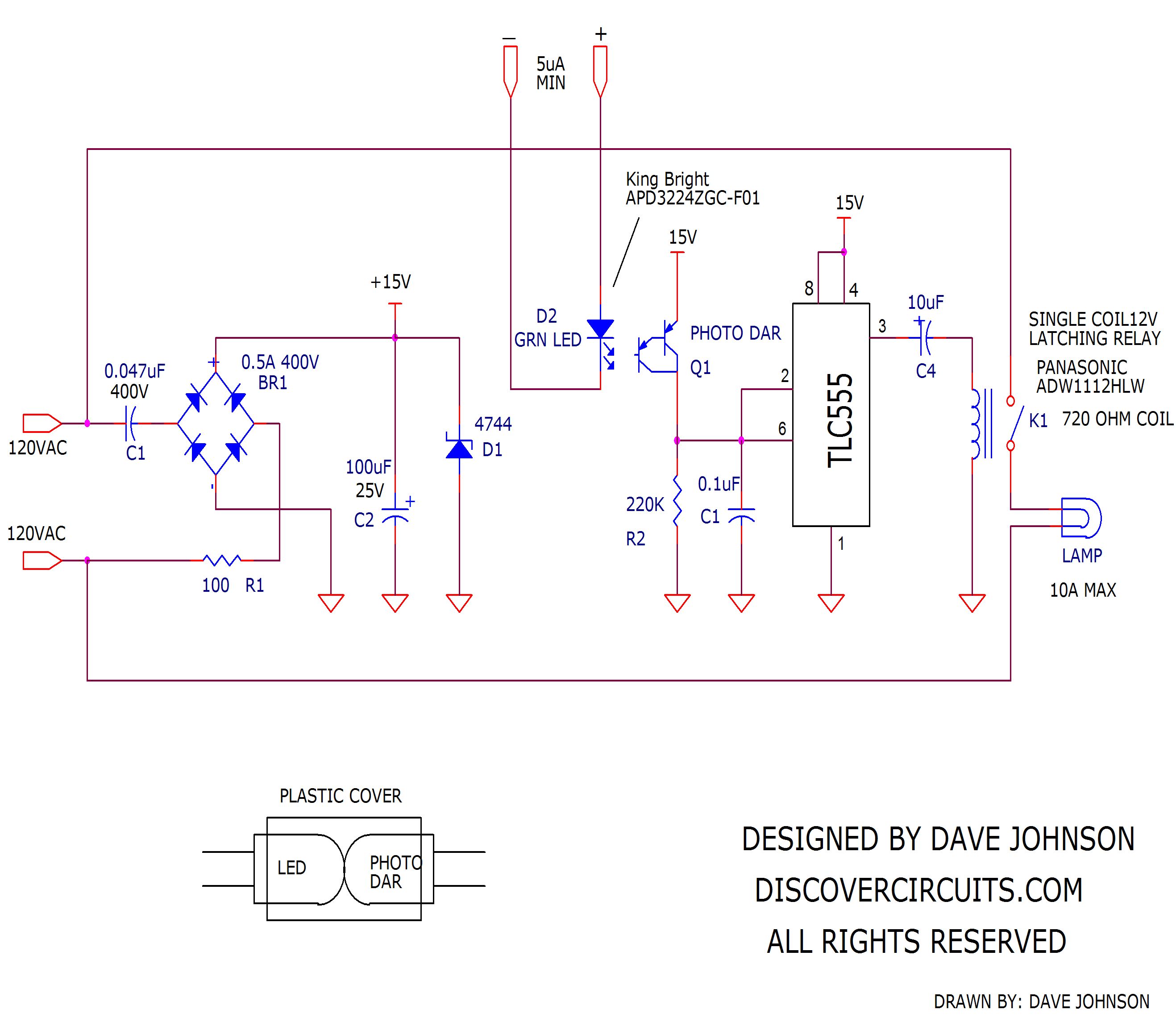
Ultra Low Current Oscillator Power Relay
-- September 23, 2017
Solid state relays have
been used for many decades as a way to control AC power to
various loads. A typical relay demands about 20ma to 50ma
of DC current to activate the relay. Also, a solid state
relay does dissipate some power and typically has to be mounted
to heat sink when the AC current exceeds 4 amps. But,
there are times, especially with battery powered control
devices, when even 20ma is too much current to keep a relay
active for a long period of time. The circuit below uses a
mechanical latching relay and a custom opto-isolator to perform
the AC switching operation. The real advantage of the
circuit is that it can switch power on and off up to 10 amps of
AC current while drawing only 10ua of current. In fact, I
have tested the circuit using just 5ua of control current. |
|
|
 |
The circuit uses a classic capacitor “voltage dropper” to capture a bit of power from the AC power line and store some energy in a capacitor. The energy is then used to activate a latching relay. The relay only needs short 20ms pulses to open or close the relay contacts. So, the average power needed to hold the relay state is very low. I use a do-it-yourself isolator drive circuit. The circuit points the end of an efficient green LED toward a photodarlington transistor. Only a tiny bit of light is needed from the LED to saturate the photodarlington light sensor. I use a 555 timer to monitor the on/off state of the light sensor, which appears as a voltage across R2. When the voltage reaches about 10v, the 555 timer output changes state and unlatches the relay. The capacitor C4 provides the needed polarity reversal and applies short current pulses to the relay coil. Be sure to select the relay coil polarity so the relay contacts latch closed, when current is fed to the LED side of the opto-isolator assembly. |
|
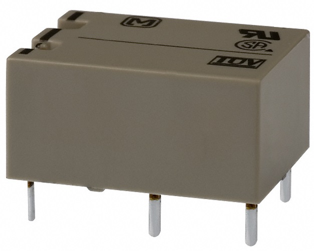
Single Coil 12v Latching Relay, 10A Rating |
| |
|
Click on Circuit Below to view PDF of Schematic |
|
 |
|
|
|
|
|
|