|
DiscoverCircuits.com -- Hobby Corner
Last Updated on:
Wednesday, June 02, 2021 03:49 AM
Hobby Circuits List
The contents &
graphics of Discovercircuits.com are copyright protected.
LINK to Dave's circuit, but DO NOT COPY any files to your WEB
SITE server |
 |
|
|
|
|
|
More Indicator Circuits
Water Well Pump Motor Indicator,
Revisited - June 29, 2017
designed
by David A. Johnson, P.E.
Several years ago I installed a box on my water well pump head. At the well head, the solar powered box flashed a very bright LED light and chirped a very load siren, whenever the pump motor was in operation. After many years of service, the box finally became corroded from rain water and died. So, I thought it was time to redesign the circuit and build up a replacement. |
|
|
|
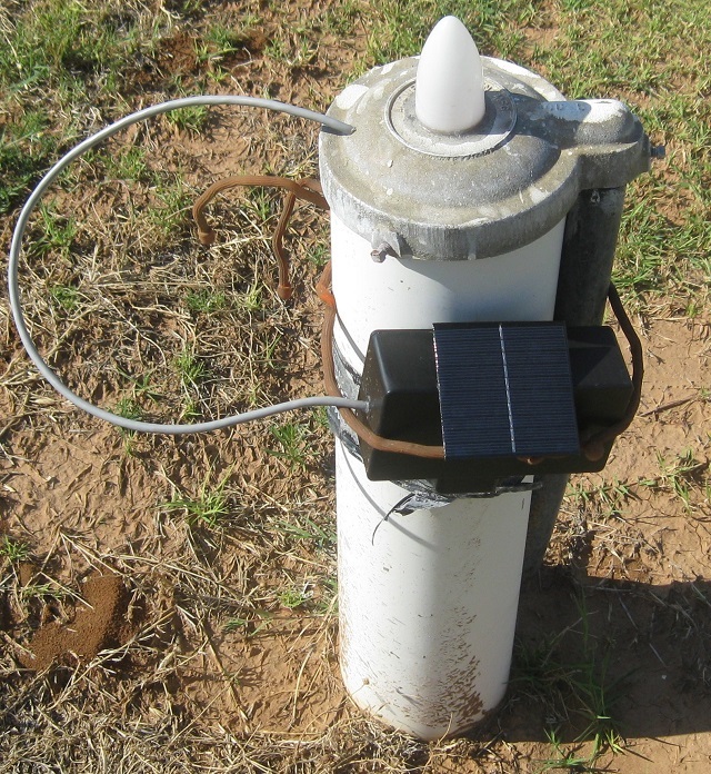
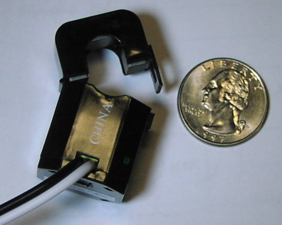
As shown to the right, the plastic box has a ten cell 5v 150ma solar panel installed on the box side. The panel is facing south and angled at 45 degrees. An external current transformer is clipped onto one of the pump motor wires going down into the well, with two turns running through the center core of the transformer. With my well pump, about 10 amps flows through the wire. The two turns through the current transformer produces about 12v AC at the output of the transformer.
When rectified, this is enough to produce about 12v DC across the 4700uF capacitor C1 as shown in the schematic below. To drive the LED and beeper day or night, I used a 3.6v battery pack, using three 1.2v AA NiMH
cells wired in series. The pack is rated at 2500ma-hours. |
 |
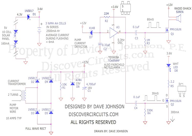
| Well Pump Motor Flasher and Beeper |
|
|
|
A signal diode D7 becomes reversed biased whenever the pump motor is in operation. This allows a Schmitt trigger 0.3Hz oscillator to begin oscillating. The square wave output of the oscillator is split into two paths. One path is connected to an n-channel FET, which drives the siren with a short 80ms pulse. The second path is connected a second FET circuit, which flashes the bright white LED with 30ms pulses. R5 limits the LED current to about 300ma peak.
A loud siren type beeper from Radio Shack was used for the noise maker. To keep the average power down, I pulse the siren with short 80ms chirps. This produces a loud but not so annoying sound. I can hear the chirp anywhere in my back yard and even in the house.
When the well pump motor stops, the AC voltage from the current transformer drops to zero. The DC voltage across C1 then slowly drops to zero with every LED flash and siren chirp. R1 eventually lowers the voltage to less than 3v, which forward biases the diode D7. With the diode biased on, the oscillator stops operating and the LED stops flashing and the beeper stops beeping. The standby current is a very low level. |
 |
 |
| Current Transformer |
Very Loud Siren |
|
|
|
Click on Circuit Below to view PDF of Schematic |
|
|
|
|
|
|
|
|