|
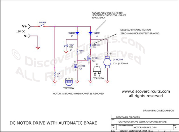
When power is applied to the hobby circuit, Q1 is
turned on. This routes zero volts to the gate of Q2, turning off Q2.
Current flows to the motor through the diode D2. When power is removed from
the circuit, Q1 quickly turns off which routes some stored charge from C1 to the
gate of Q2. This turns on Q2, which provides a heavy current path for the free
spinning voltage emerging from the motor windings. The value of R3 can be
selected for any desired braking action. The fastest braking time occurs when
the resistance of R3 is zero ohms. |
|