|
DiscoverCircuits.com -- Hobby Corner
Last Updated on:
Tuesday, June 01, 2021 03:06 PM
Hobby Circuits List
The contents &
graphics of Discovercircuits.com are copyright protected.
LINK to Dave's circuit, but DO NOT COPY any files to your WEB
SITE server |
 |
|
|
|
|
|
|
More
Piezoelectric Circuits,
Buzzer Circuits,
Switch Circuits
|
|
Piezoelectric
Tap Switch |
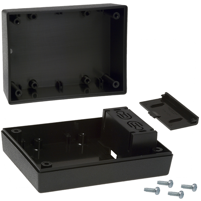
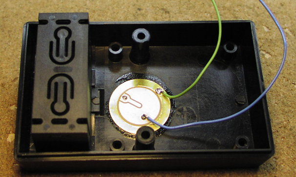
| This
circuit uses a flat piezoelectric wafer, glued inside a plastic box, as a finger tap
sensor. With each tap of a finger to the box holding the wafer, the circuit
turns on and off AC or DC power to an external device. The circuit is powered
by a 9v battery and drives a single coil 5v latching relay with a 10 Amp contact
rating. The relay can switch AC or DC power. In standby mode the circuit
draws a low 1ua. |
|
|
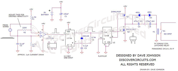
A firm finger tap to the plastic box cover causes the piezoelectric
wafer to produce multiple voltage pulses. The pulses are fed to a low power
voltage comparator. The comparator converts the low voltage pulses into 9v
pulses. Those pulses are fed to the clock input of one half of a CD4013 dual D
flip/flop. One section is configured as a half second one shot. The
second half is wired as a standard flip flop. With this circuit, the flip/flop
changes state with each finger tap to the box, holding the circuit. The output
of the flip/flop is connected to a dual FET push-pull driver circuit, which feeds
power to a pair of capacitors. The capacitors are wired in series with
parallel diodes. This forms a 235uF non-polarized capacitor. With this
charge pump configuration, the power pulses from the FETs feed either a positive
pulse to the relay coil, to latch it, or a negative pulse to unlatch it. The
pulse lasts long enough to fully open or close the relay contacts. |
|
|
|
|
|
|
Click on Circuit Below to view PDF of Schematic |
|
 |
|
|
|
More
Piezoelectric Circuits, Buzzer Circuits,
Switch Circuits
Hobby Circuits List
eMail David A.
Johnson, P.E. about this circuit |
|
|