|
 |
DiscoverCircuits.com -- Hobby Corner
Last Updated on:
Tuesday, June 01, 2021 03:06 PM
Hobby Circuits List
The contents &
graphics of Discovercircuits.com are copyright protected.
LINK to Dave's circuit, but DO NOT COPY any files to your WEB
SITE server |
|
|
|
|
More
AC Power Control Circuits |
|
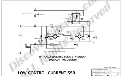
SOLID STATE
RELAY REQUIRES ONLY 50uA DRIVE CURRENT
|
|
Most solid state relays require at
least 5ma and often more input control current, to fully turn on the device.
But such current levels often force battery powered circuits to use excessively
large batteries. The relay hobby circuit shown below demands only 50uA of
input current. This about 100 times lower than that needed by a typical
optically isolated solid state relays. The circuit uses a combination of a
high current TRIAC and a very sensitive low current SCR, to control up to 600 watts
of power to a load, while providing full isolation and transient protection.
|
|
|
|
|
At the heart of the
circuit is a Darlington type opto-isolator A1 from NEC. This device needs only
50uA of current through the LED section to activate the Darlington side. A
bridge rectifier and a couple capacitors, strips off a bit of current from the
120vac line, through the load. A zener diode limits the generated DC voltage
to 8v. When the opto-isolator is turned on, current is routed to the gate of a
sensitive SCR. When turned on, the SCR routes current pulses to the main
control TRIAC, through a bridge rectifier. A 15v zener delays the trigger
point of the TRIAC slightly, so a minimum 30 volts peak to peak is always available
to maintain current to the SCR circuit. |
|
|
|
Click on Drawing Below to view PDF version of Schematic |
|
 |
|
|
|
More
AC Power Control Circuits
Hobby Circuits List
eMail David A.
Johnson, P.E. about this circuit |
|
|