|
DiscoverCircuits.com -- Hobby Corner
Last Updated on:
Tuesday, June 01, 2021 03:06 PM
Hobby Circuits List
The contents &
graphics of Discovercircuits.com are copyright protected.
LINK to Dave's circuit, but DO NOT COPY any files to your WEB
SITE server |
 |
|
|
|
|
|
|
More
Latch Circuits
Light Flasher Circuits
Relay Circuits |
|
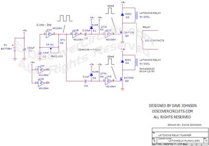
Universal Flasher Circuit Using a
Latching Relay
designed
David Johnson, P.E. |
| Latching relays are nifty
devices. Most contain two separate coils. When a voltage is applied to
one coil the relay latches in one state and stays in that state until voltage is
applied to the unlatch coil. Since the latching and unlatching pulses only
need to last about 25 milliseconds, it is possible to control a sizeable amount of
power using little energy. |
|
|
There are many applications where you would like something to be cycled on and off.
Perhaps you want to flash an advertising sign on and off or maybe you want to flash some
Christmas trees lights. This kind of flashing need is a perfect application for a
latching relay. The hobby circuit below controls a latching relay from a simple 9v
battery. The time between flashes can be adjusted from 0.25 seconds to 5 seconds. |
|
The electronic circuit is powered by a 9v battery.
It uses a single 74C14 (CD40106) CMOS
hex Schmitt trigger inverter logic IC.
One inverter is configured as a square wave generating oscillator. I included
a 1M variable resistor in the oscillator circuit so the frequency could be adjusted
from about 0.1Hz to about 2Hz. Other on/off times can also be achieved by
changing the value of C2.
The output
of the oscillator is split into two 25ms pulse generator circuits. One circuit
pulses the latch relay coil, when the oscillator output swings from zero volts to
+9v, while the other circuit generates a pulse for the unlatch coil, when the
oscillator output swings from +9v to zero volts. Two n-channel FETs drive the
two different coils. The relay selected is rated for 10 Amps of current.
This should be heavy enough for most flashing applications. The relay contacts
are wired into the device to be flashed on and off. The contacts can handle AC
or DC loads. |
|
|
|
|
Click on Circuit Below to view PDF of Schematic |
|
 |
|
|
|
More
Latch Circuits Light Flasher
Circuits Relay Circuits
Hobby Circuits List
eMail David A.
Johnson, P.E. about this circuit |