|
300 MHz Prescaler - A preamp that drives the CMOS
counter input and a divide by 10 prescaler to extend the range of A Little More Serious Frequency Meter. The MCT10280 prescaler can be set to divide by 80, 40, 20, or 10, as a function of which pins are tied to the power supply. I set this one to divide by 10 since it is adequate for my needs, and the mental calculation of multiplying the meter reading by 10 is not taxing. One problem with the MCT10280 is that if it doesn't have an adequate input, the output is very noisy, which shows up as counts in the couple MHz range on the frequency meter. This noise shows up if the signal amplitude the signal frequency is too low. For this reason, I only intend to use the prescaler with inputs between 10 MHz and 300 MHz__
300/1200 baud BAYCOM MODEM (revision and improved) - Ham Radio - Modems and Soundcard interfaces __ Designed by Guy Roels ON6MU
300m FM Transmitter - This FM transmitter circuit is very simple and it has a acceptable transmission . The signal transited from this FM transmitter circuit can be received at almost 300 meters in open air . The circuit require a 3volts operating voltage and can be tuned anywhere in the FM band. The coil should be about 3mm in diameter__
300m FM Transmitter - This FM transmitter is about the simplest and most basic FM transmitter it is possible to build and have a useful transmitting range. it is surprisingly powerful despite its small component count and 3V operating voltage. it will easily transmit over 300 meters in the open air and even more with higher voltage supply. The circuit we use is based on a proven Australian design. it may be tuned anywhere in the FM band. Or it may be tuned outside the commercial M band for greater privacy. Of course this means you must modify your FM radio to be able to receive the transmission or have a broad-band FM receiver. The output power of FM transmitter is within the legal limits of many countries. However, some countries may ban all wireless FM transmitters without a license. it is your responsibility to check the legal requirements for the operation and to obey them. FM transmitter is constructed on a single-sided printed circuit board PCB.__
300mW FM Transmitter with 2SC2538 - The above FM transmitter has RF output power of 300 mW and covers more than one kilometer distance. Frequency adjustment is accomplished with MV2105 varactor diode and R7 10K potentiometer.2SC2538 is a class C 300mW amplifier.__
303MHz TRANSMITTER with 32kHz Crystal - We have covered 27MHz (and 49MHz) links on P1 and P2 of this article and shown how to produce a simple circuit (or buy a toy for less than $10.00) and get 4 or 5 channels.
We also showed how to produce on/off from a single channel and how to detect 27MHz with a Field Strength Meter __ Designed by Collin Mitchell
30W VHF FM Amplifier for 88-108 MHz with BLF245 MOSFET - The achievement of this 30-watt amplifier has been designed to take place on a heatsink microprocessor PC equipped with its fans, the advantage of this method of cooling has been selected for the fact that (French __
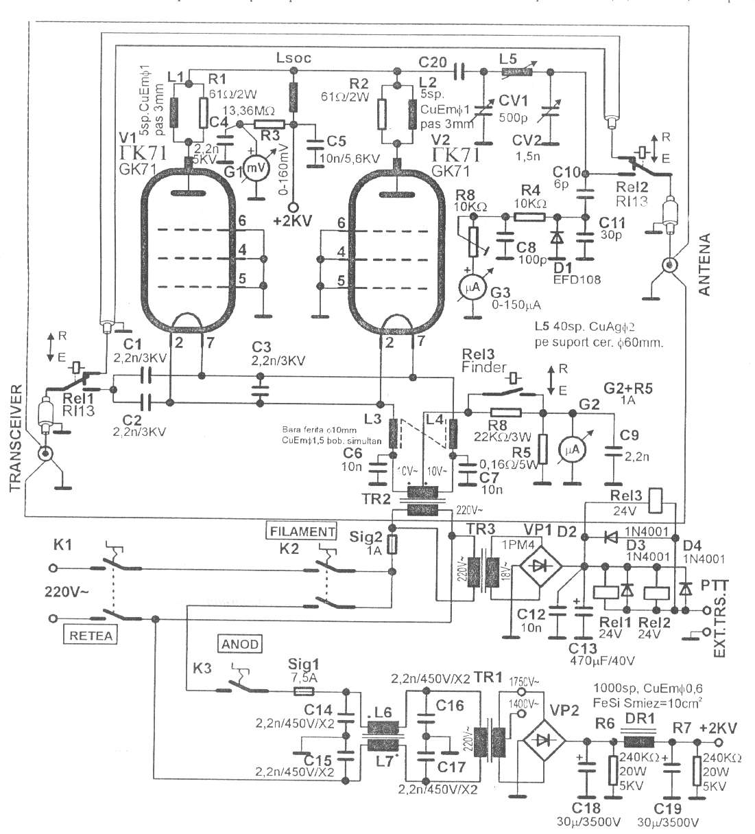
350W QRO with GK71 for 160-15m - Schematic only, no circuit description __ Designed by © 2001 - YO5OFH, Csaba Gajdos
35kHz Magnetic-Radiation Remote-Control - Short-range 35KHz operation, single-channel units; Simple circuitry, no outer antennas required __ Contact Flavio Dellepiane, fladello @ tin.it
3cm SSB transverter - We describe here one of the two 10GHz SSB transverters we built around pieces of LNBs for satTV. Converts 3cm ham band from/to 432MHz iF, has 1W TX power and its Local Oscillator can be locked either to an internal OCXO or to an external frequency standard. __ Designed by Andrea IW9HJV and Johnny IW9ARO
3Khz Filter + Audio Amplifier - This circuit is the audio amp section for a complete optical transmitter. The circuit amplifies and filters the voice audio signals from an electret microphone. The circuit is described in more detail in . . . Hobby Circuit designed by David A. Johnson P.E.-June, 2000
3V FM Transmitter - The objective of this 3V FM Transmitter design is to provide a simple low-power transmitter solution for broadcasting audio from various audio sources. This transmitter transmits audio using small sensitive microphone. Transmitter's frequency, as built is tunable via 15pF trimmer to the desired frequency, and the coil is embedded on the circuit board. This implementation is adapted to rebroadcast the output of a CD player, television receiver, or radio receiver. I use this transmitter so that I can move about the house and listen to my favorite programs without disturbing others. Within and the house, I find that I can get 50 to 100 meters away from the transmitter with the small pocket FM receiver I carry in my shirt pocket.__
3V FM Transmitter for 88MHz to 108MHz - The important part of the circuit is formed of the Colpitts type oscillator. C3, C4, C5, C6, CD1-CD2 and L1 determines the frequency. BF982 and dual gate MOSFET are active parts in oscillator. When the input impedance of the MOSFET gate inputs are high, LC tank is not affected. However transistors force the LC tank and cause phase shift. Two driver stages are added to isolate the antenna from oscillator. First stage (BF199) amplifies the low signal of the oscillator and works as a constant load. The second stage (BFR90) amplifies the signal going through the antenna some more. __
3W FM Transmitter - This is the schematic for an FM transmitter with 3 to 3.5 W output power that can be used between 90 and 110 MHz. Although the stability isn't so bad, a PLL can be used on this circuit. This is a circuit that I'vebuild a few years ago for a friend, who used it in combination with the BLY88 amplifier to obtain 20 W output power. From the notes that I made at the original schematic, it worked fine with a SWR of 1 : 1.05 (quite normal at my place with my antenna). __ Designed by Aaron Cake
4 Band Double Tuned Preselector - The circuit requires an RF input which can be from a longwire or a loop antenna. The Preamplifier has a range from 550kHz (Medium Wave) up to 30 MHz in the SW band. The input Switch S1, applies voltage to a set of relays which switch in the appropriate coils __ Designed by David Sayles
4 channel 433MHz remote control transmitter / receiver based on SM5162 & SM5172 chips - The radio control uses pre-calibrated 433 MHz transmitter and receiver modules. The SM 5162 presents a code to the transmitter module depending on the status of the input switches. The 555 is configured to provide a regular pulse to the 'transmit enable' (pin 15) of the SM 5162 - this pulse runs at a frequency of about 7 Hz (the LED will flash with each transmission). This means that the transmitter will update the code transmitted 7 times a second. __ CdS Electronic
4 channels RF wireless transmitter and receiver - This is a very simple Wireless RF transmitter circuit that consists of the Holtek HT-12E encoder chip and AM 418MHZ-transmitter module (WZ-X01, other similar device can be used). Using the hybrid RF xmit/receive modules make building the RF remote control a lot easy __ Contact info @ wzmicro.com
4 MHz Amplitude Modulated RF Source - A while back I needed an amplitude modulated signal source at 4 MHz. This circuit was literally thrown together with parts laying on the bench. I built it dead bug style on a piece of copper clad board. it should work with little or no modification, other thano get it to oscillate, and at higher frequencies, you might have to reduce the capacitor values a little. Just be __ Designed by Dick Cappels
4 Transistor Tracking Transmitter - Schematic and parts list only, no circuit description included. __ Designed by Tony van Roon VA3AVR
4 Transistor Transmitter - This circuit provides an FM modulated signal with an output power of around 500mW. The input Mic preamp is built around a couple of 2N3904 transistors, audio gain limited by the 5k preset. The oscillator is a Colpitts stage, frequency of oscillation governed by the tank circuit made from two 5pF capacitors and the inductor __ Designed by Paul K Sherby
4 Watt FM Transmitter - This is a small but quite powerful FM transmitter having three RF stages incorporating an audio preamplifier for better modulation. t has an output power of 4 Watts and works off 12-18 VDC which makes it easily portable. it is the ideal project for the beginner who wishes to get started in the facsinating world of FM broadcasting and wants a good basic circuit to experiment with __ Designed by Gundalla
4 Watt FM Transmitter - The following is a simple yet powerful 4W FM transmitter which is tunable to 88-108MHz frequency. Connect to your ipod/computer, etc. When this was first made, I only had a 2N2219A on hand, which resulted in a lower RF output. I have since swapped out the transistor for a 2N3866 for full 4W output at around 15VDC supply. in order to achieve a high output level, you will need a well tuned antenna, and a large heatsink to dissipate the heat from T2 transistor. Transmitter was mounted in metal enclosure and works extremely well.__
40 Meter Direct Conversion Receiver - Using the circuit of direct-conversion receiver described here, one can listen to amateur radio QSO signals in CW as well as in SSB mode in the 40-metreband. The circuit makes use. __
40 Meter, 5 Watt QRP Transmitter - As ham operators, we like to broaden our horizons by trying something new. There is nothing more satisfying about this hobby than building your own transmitter. The circuit in figure 1 is a crystal controlled CW transmitter with at least 5 watts of power. (The prototype generated 7 ˝ watts) This circuit was built on a Radio Shack universal board (276-168B) and worked extremely well the first time __ Designed by Radio Amateur Society of Norwich
40 Watt FM Transmitter Amplifier - Building two stage 40 Watt FM Transmitter Amplifier. RF input power should be between 0.5 and 1 watt. Amplifier is powered by 28V power supply. The diagram shows a 2N3375 driving a 2N5643 but there are many other transistors that will work. I used these two transistors just because they were cheap at the time. if any of the variable capacitors are at full capacitance you can pad them out with a fixed ceramic capacitor of suitable value. Extra capacitance also might be needed on the base of the transistors (I had to add 3 100pF capacitors on the base of the 2N5643). The transistors are bolted to a piece of right angle aluminum which is fixed to the metal chassis to dissipate heat effectively.__
400mW VCO FM transmitter - Schematic + Parts List + PCB __ Jan Kolar
40khz TV-VCR Light Source Repeater - This circuit is designed to be placed directly in front of a standard TV or VCR remote. The exiting light pulses produced by the circuit match the pulses from the remote but are about 10 times more powerful. Using the device, the remote can operate a TV or VCR over three times the normal distance. . . Circuit by David A. Johnson P.E.-June, 2000
40mW FM TRANSMITTER - The transmitters on my homepage seem to be quite popular, especially those intended for the 88 - 108MHz FM band. I must really confess that I also favor this broadcast band, mainly because it is so easy to find signals on the workshop radio. Everyone has an FM radio, and it is fun to play with. Experimental antennas and the like can all be developed in this band since there are a huge range of "beacons" all transmitting just for my benefit :-). Basic oscillators also are easy to fault-find in this frequency band, and then later modified for other VHF bands. The V5 FM Wireless Microphone is a 10mW transmitter that featured a coil fabricated on the PCB itself. This made the project easy to duplicate and removed "microphony" (the ability of coils to act as a microphone with spring-line reverb). But as several people have already commented, although more stable than most other similar kits and projects, the frequency still does vary with battery voltage. in just one session it can vary by 200kHz when a cheap "Mighty Atom" battery falls to 8 volts.__
432 MHz kilowatt Amplifier - Schematic only, no circuit description __ Designed by W1QWS
433MHz Super Remote Control - Using a PIC 12F683 and a few transistors, it is theoretically possible to boost the power to a standard 433 MHz remote transmitter module. (Note hypothetical image at right).
This design utilized 10 Pulse Coding for maximum range with minimal power draw. Very short pulses are generated using a voltage multipier circuit described below. __ Designed by Luhan Monat-Mesa Arizona
433MHz UHF Remote Switch - ideal for remote control of practically anything you like and with a range of more than 200m, this wireless transmitter and receiver pair use pre-built UHF modules that make it easy to construct and use.__ SiliconChip
434MHz short-range communications - article from Elektor 1998/5. __ Designed by Peter Jakab
434MHz transmitter using SAW resonator - Schematic only __ Designed by Peter Jakab
49MHz Walkie Talkie - Lots of people are requesting walkie-talkie and RF remote control schematics, so here is some. Building se circuits needs special equipment and expertise in RF circuits. if you are going to experiment with se circuits, please note that I did not build __ Designed by Peter Jakab, Electrical Engineer, Engineer of Informatics
4-CH Remote Control - You can construct your own long range infrared (iR) wireless remote using Motorola's MC145026 emitter and MC145027 detector chips. With your remote you can control devices up to 20 feet (7 meters) away. It operates similarly to a TV remote. You just point the emitter at the detector, push a transmit button. The detector then interprets your data signal. You can use this circuit to remotely turn on/off devices (like a motors, relays, home appliances). __ Designed by Boondog web site
4km FM Transmitter - This is a VCO FM Transmitter. With good antenna (dipole placed outdoor and high) the transmitter has very good coverage range about 500 meters, the maximal coverage range is up to 4 km. To calibrate for maximum power connect 6 V / 0, 1 light bulb to the output and use R1 to tune the right frequency, adjust L1 coil if necessary. Then use C14 and C15 to adjust the highest power (the highest light of the bulb). Then you can connect antenna and audio signal. Adjust R2 until the audio sounds as loud as the other stations.__
4-Transistor Transmitter - 4 Transistor Transmitter - Circuit + Parts List + Notes __ Designed by Paul C. Sherby
4W FM Transmitter - This is a small but quite powerful FM transmitter having three RF stages incorporating an audio preamplifier for better modulation. t has an output power of 4 Watts and works off 12-18 VDC which makes it easily portable. it is the ideal project for the beginner __ Designed by © smart kit electronics
4-Watt AF Amplifer - I have recently included a page about AF amplifiers for use with Homebrew rigs. in this I mentioned that I may include a practical one-watt circuit, complete with PCB foil and layout. Here it is, but I have taken the liberty of engineering it to provide 4-watts of AF output and with a frequency response almost suitable for Hi-FI applications __ Designed by Harry Lythall-SM0VPO
4-way remote control uses series transmission - 01/18/01 EDN Design ideas: A simultaneous four way remote-control system adheres to size, cost, and reduced-complexity constraints and uses a series transmission to drive parallel loads (Figure 1). You can use. PDF has several circuits, scroll down. Design by JM Terrade, Clermont-Ferrand, France
|