|
Power-On Time Delay Relay - Here's a power-on time delay relay circuit that takes advantage of the emitter/base breakdown voltage of an ordinary bi-polar transistor. The reverse connected emitter/base junction of a 2N3904 transistor is used as an 8 volt zener diode which creates a higher turn-on voltage for the Darlington connected transistor pair. Most any bi-polar transistor may be used, but the zener voltage will vary from about 6 to 9 volts depending on the particular transistor used. Time delay is roughly 7 seconds using a 47K resistor and 100uF capacitor and can be reduced by reducing the R or C values. __ Designed by Bill Bowden Regulated 12V Supply - This circuit above uses a 13 volt zener diode, D2 which provides the voltage regulation. Aprroximately 0.7 Volts are dropped across the transistors b-e junction, leaving a higher current 12.3 Volt output supply. This circuit can supply loads of up to 500 mA. This circuit is also known as an amplified zener circuit __ Designed by Mick Devine
Simple Circuit Monitors battery voltage - 11/21/96 EDN Design Ideas: The circuit in Figure 1 monitors four NIC d rechargeable batteries and causes the LED to flash if the voltage of the batteries goes lower than 4V. The circuit consumes only 8 mA of current under normal operating conditions. IC 1 is an eight-pin IC that includes an op amp, a comparator, and a 1.2V zener diode. The zener diode connects to the negative input of the comparator in the IC as a reference. R6 and R7 divide the battery voltage Design by Yongping Xia, Philips Lighting Electronics Co, Torrance, CA
Sunrise Lamp using 120VAC 60 Watt Lamp - in this circuit, a 120VAC lamp is slowly illuminated over a approximate 20 minute period. The bridge rectifier supplies 120 DC to the MOSFET and 60 watt lamp. A 6.2K, 5 watt resistor and zener diode is used to drop the voltage to 12 volts DC for the circuit power. The bridge rectifier should be rated at 200 volts and __ Designed by Bill Bowden
The Amplified Zener - A 13 volt Zener diode will work well for charging a 12 volt battery on Standby use. Or use a 14 volt zener a diode for a Standard 14.6 volt charge. __ Designed by G.L. Chemelec
Time Delay Relay-Power OFF - The two circuits below illustrate opening a relay contact a short time after the ignition or ligh switch is turned off. The capacitor is charged and the relay is closed when the voltage at the diode anode rises to +12 volts. The circuit on the left is a common collector or emitter follower and has the advantage of one less part since a resistor is not needed in series with the transistor base. However the voltage across the relay coil will be two diode drops less than the supply voltage, or about 11 volts for a 12.5 volt input. __ Designed by Bill Bowden
Time Delay Relay-Power ON - Here's a power-on time delay relay circuit that takes advantage of the emitter/base breakdown voltage of an ordinary bi-polar transistor. The reverse connected emitter/base junction of a 2N3904 transistor is used as an 8 volt zener diode which creates a higher turn-on voltage for the Darlington connected transistor pair. Most any bi-polar transistor may be used, but the zener voltage will vary from about 6 to 9 volts depending on the particular transistor used. Time delay is roughly 7 seconds using a 47K resistor and 100uF capacitor and can be reduced by reducing the R or C values. __ Designed by Bill Bowden
Two-Watt Switching Power Supply - in this small switching power supply, a Schmitt trigger oscillator is used to drive a switching transistor that supplies current to a small inductor. Energy is stored in the inductor while the transistor is on, and released into the load circuit when the transistor switches off. The output voltage is dependent on the load resistance and is limited by a zener diode that stops the oscillator when the voltage reaches about 14 volts. Higher or lower voltages can be obtained by adjusting the voltage divider that feeds the zener diode. The efficiency is about 80% using a high Q inductor. __ Designed by Bill Bowden
Using the LTC1325 Battery Management Ic - AN64 App Note 64 details characteristics of various battery types and appropriate charging management schemes. The LTC1325 battery management IC is highlighted along with information for applying it to any type battery. Techniques and circuitry for conditioning, charging and monitoring NIC d, NiMH
, Li-ion and Lead-Acid batteries are presented. __ Linear Technology/Analog Devices
Zener diode & MM ICs produce true broadband noise - 10/14/99 EDN Design Ideas: A broadband source of white noise can be useful for measuring and testing communications equipment. The source in Figure 1 is simple and produces a large noise signal at its output terminals. The circuit Design by Lukasz Sliwczynski, University of Mining and Metallurgy, Institute of Electronics, Krakow, Poland
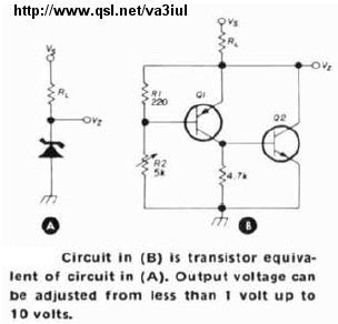
Zener Diode Emulator-WA5EKA - Schematic only __ Designed by va3iul
Zener Diode Protects FPGA Inputs - in a pinch, a Zener diode can save time and prevent a board redesign. Design by Rick Collins, Arius, Frederick, MD
Zener Diode Tester - This zener diode tester can be used to check zener diodes of 3.3V to 18V. The breakdown voltage of the unknown zener diode is indicated on the precalibrated dial of potmeter...__ Electronics Projects for You
Zener level-shifter drives high-side switch - 06/16/2014 EDN Design Ideas: Simplify a high-side driver by replacing a transistor with a Zener diode. Microcontrollers, the heart of all modern electronic gadgets, are increasingly powered with sub-5V power supplies. This complicates the control of external loads powered by higher voltages. Design by Dhananjay Gadre & Nidhi Sharma
Zener regulator - A 13 volt Zener diode will work well for charging a 12 volt battery on Standby use. Or use a 14 volt zener a diode for a Standard 14.6 volt charge. __ Designed by G.L. Chemelec
Zener test serves as DC source - 11/25/04 EDN Design Ideas: This design idea describes a versatile test circuit for zener diodes after yet another misread zener diode had infiltrated the ranks of 1N4148 diodes assembled on a pc board. As a bonus, the circuit can serve as a moderate-voltage, Design by John Jardine, JJ Designs, West Yorkshire, UK
Zener tester - if no zener (D2) is connected across C1 and S1 is switched on, the output rises rapidly to 45V DC. This voltage can be measured with a DVM. When an unknown zener is connected across C1, output will be equal to the zener voltage. if a normal diode (or a zener diode with zener voltage > 45 V) is hooked up, the DVM will measure 45 V. if a diode is connected with the wrong polarity, the meter will indicate 0.6 or 0.7 V (even lower if the diode is a germanium or Schottky type). __ Designed by Aren van Waarde
Zener Value Evaluator - Using this simple circuit and a known-value zener diode, you can find the breakdown voltage value of any zener diode. The circuit is divided into two sections: zener evaluator and display...__ Electronics Projects for You
Zener-based - Type 1 (Voltage Controlled) Solar Engine - This design uses a Zener diode to determine the voltage trip level. Simple variants of this design use LEDs or plain old diodes in series to accomplish the same thing. __ Designed by Wilf Rigter
Zener-based solar engine - Voltage-Controlled Solar Engine:This design uses a Zener diode to determine the voltage trip level. Simple variants of this design use LEDs or plain old diodes in series to accomplish the same thing. __ Designed by Wilf Rigter and Eric Seale |