|
Challenge:
Design
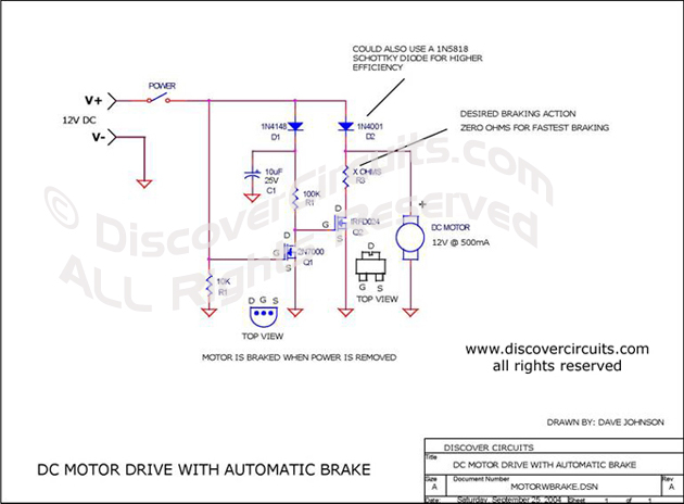
a simple circuit that would automatically apply an electrical brake to a motor, when DC power
is removed.
Solution:
My
solution is shown below. When the power switch is closed, the gate voltage of Q1 turns
Q1 on. The drain of Q1 swings low, turning off Q2. Current flows freely into the DC
motor with only one diode drop from D2. When the power switch is open. The gate
voltage of Q1 swings low, causing the drain of Q1 to swing high. This turns on the transistor
Q2. With Q2 on, the resistor R3 is switched in parallel with the motor, producing a
braking action. The value of R3 can be selected for the desired braking action. A
zero ohm resistance will produce the fastest slow down of the motor. The circuit below
is good for about 500ma of motor current. A Q2 transistor with a lower on resistance
would be needed for bigger motors. Also, D2 would need to increase in size.
|