|
The home designer did not specify how this kind of lighting control was to
be accomplished could Wily help?
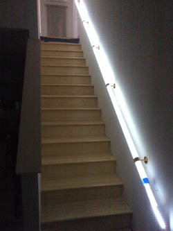
There were two different handrail designs. One design called for a
straight rail while the other was L shaped. The total distance between the top and bottom
of the railing was 15 feet. Wily knew that most capacitance switches would not be
able to deal with such a large separation between the two ends. Also, there was not
much room inside the two ends of the rail where the touch switch was to be located.
Wires for the two touch buttons and the AC powered LED strip wire were to be fed through
one of the brass brackets holding the rail in place. The original idea was to place
the 12vac power supply and the capacitance switch up in the ceiling, well away from the
stairs. But, Wily knew that such a long wire would not be wise in a capacitance type
switch circuit. Some kind of remote but tiny capacitance sensing circuit was needed.
Then, one sensor could be attached to each of the two brass touch buttons and the output
signal could then be routed to a main circuit, placed next to the AC power supply some
distance away. Wily had experimented with such circuits in the past and thought that
he could use one of those circuits in this situation. The contractor said that he
would need about 100 such systems. Wily decided to take on the project.
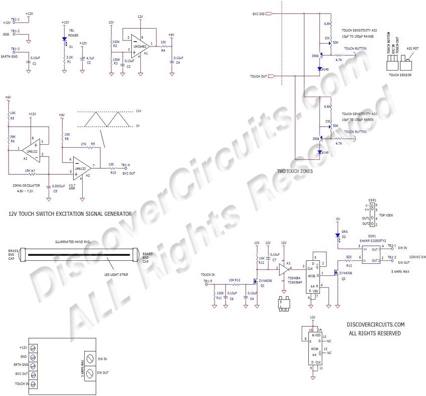
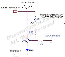
It had been decades since Wily had performed some of the experiments for
remote capacitance sensing. The basic sensor circuit is shown below. A 20KHz,
12 volt peak to peak triangle shape waveform is used to provide both power to the single
transistor circuit and the critical AC excitation signal. When sufficient capacitance was
connected between the transistor base and an earth ground reference, the transistor
circuit would begin to route part of the triangle signal to the collector. The diode
turns the pulses into a DC voltage. That output is then routed to a simple filter
network, located some distance away. After that, it was a simple task to add some
additional filtering and an on/off flip/flop circuit. The flip/flop circuit would
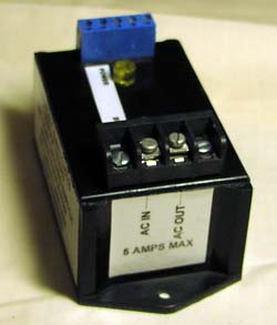
then turn on and off a solid state relay. The relay would switch on and off 120vac
power to the 12vac power supply. The touch switch circuit would be powered by a small 12v
DC power adapter.
|
The above circuit is been
corrected on 7/5/2012 |
The complete touch
switch circuit is shown below.
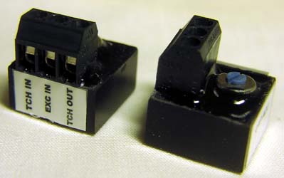
Wily placed the remote capacitance sensor circuit inside a small
potting shell, which contained a three screw terminal block and a single turn
variable resistor.
The variable resistor allowed
the capacitance needed to activate the switch to be set from about 10pf to 170pF.
The whole sensor assembly
measured just about a half inch cube and could easily fit neatly inside the end of
the hand rail.
The two buttons were connected
in parallel, so touching either button would toggle the flip/flop. |
|