|

|
|
|
|
|
|
|
|
Wily Widget at Work
Single Lead-Acid Cell Voltage Monitor, July
7, 2012 |
 |
Wily was just finishing his
morning cup of coffee when his phone range. The caller was the owner of a large
photovoltaic power system installation company. They installed systems for business
owners and home owners who wanted a complete solar power system, using photovoltaic solar
panels mounted on the roof of their home or building. Most of the systems the
company installed were grid tied, which did not use any storage batteries. But, sometimes,
the company did install systems with a large battery for backup power and for off-grid
systems. The caller explained that the battery banks used large lead-acid cells to
harvest the energy made in the daytime by the solar panels, so that energy could later be
used at night. |
| He explained that many of his
business customers also used the battery as a backup power source for their computer
systems, so they would always have power, even if utility power were lost. The reason for
the call was a concern about battery health monitoring. As in all battery
installations, a single bad battery cell could bring down the whole energy storage system.
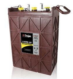
Most of the systems used 12 or 24 big cells. Some of the larger cells had a storage
capacity of 2000 Amp-hours. Under normal operations, the battery was seldom used
below 50% of its capacity. But when the battery was used below that figure, the voltage of
the weakest cell could drop below a critical level. This could often lead to future
trouble. The DC to AC inverters the company used to convert the DC from the battery bank
to AC line voltages all had a safety feature built in. The inverter would disconnect
any electrical load from the battery when the total battery voltage dropped below a
certain level. But, the system did not indicate if any of the cells had a lower than
normal voltage during these deep discharge cycles. Could Wily come up with a way for
the owner to see if any cell dropped below a critical voltage? Replacing a weak cell
could prevent future problems. This didn’t seem like a complex task, so Wily decided to
take on the project. |
| The solar power company thought
that a simple red/green LED indicator light would be all that would be needed.
A small module would be connected across the terminals of each battery cell.
A green LED would turn on, to indicate that the cell voltage was above 1.8v.
The company wanted the light to turn red, and latch in that mode, if the cell
voltage ever dropped below 1.8v. With such voltage monitors installed, the
owner could quickly glance at the battery bank and see if any cells had ever
reached the low voltage mark. If it had, it could mean that the cell
needed to be replaced. A small pushbutton switch or perhaps a magnet hall
sensor inside the module could be used to reset the alarm mode. With a
hall sensor, the module could be reset with a magnet. This would allow the
module to be fully encapsulated. The two wires connected to the monitoring
circuit could be connected to the large cell electrodes using magnets. The
hard lead electrodes of the cells were connected to jumper cables using copper
clad steel screws. The magnet approach would mean the contact to the
electrodes could be made without screws or clamps. |
|
|
|
| The circuit that
Wily came up with is shown below. He used a low voltage reference and a voltage
comparator from National Semiconductor to monitor the battery voltage. To insure
enough voltage to turn on a green LED, Wily chose a tiny charge pump type voltage
converter IC from Texas Instruments. This device efficiently converts the 1.8v from
the battery into 3.3 volts. A dual Schmitt trigger inverter IC, also from Texas
Instruments, was used to latch the normal and low battery states and a Honeywell Hall
switch was used as reset switch. A small magnet held to the side of the plastic
module holding all the parts would unlatch the alarm condition. When everything was
working properly, a bright green LED light would turn on. If the battery voltage
were to drop below 1.8v, the green light would switch to red and stay in that mode, until
reset with a magnet. The complete system was housed in a small plastic box, less
than a cubic inch in size. Epoxy was used to encapsulate the circuit components. |
| |
|

|
 |
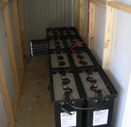 |
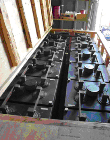
| 1000 Amp -Hr Cell |
48v 1000 Amp-Hr
Battery |
| |
| Battery placed in well
ventilated shed. Electronics can prevent the complete battery from being
overcharged or discharged too deeply but the system does not point to a single weak
cell. |
|
 |
Use a low power, low
voltage comparator with a voltage reference to turn on a red LED when the
voltage was below x volts. A reset button would be pressed to restore the
circuit to a standby mode. The red LED would be latched on when the
voltage was below x volts. Perhaps a green LED would be turned on for
normal operation.
Careful section of a
green LED which produces acceptable light with just 1.75v.
Red LEDs no problem.
1.75v for a cut-off
voltage. |
|
|
|
|
|
|
|