HOME Schematics Hobby Corner Dave's Circuits Electronic Resources Book Corner Contact Info


Wily Widget

  Previous Issues

Medical Fluid Detector

Wily was at his desk when he got a call from a California medical company.  They needed a simple fluid detector but could not figure out how to design it themselves.  Would Wily have time to help them? 

The company made several kinds of fluid delivery systems.  Most were used to infuse chemotherapy drugs to a patient.  Instead of the usual IV drip method, where the fluid is held in bags, their system drew fluid from half liter to full liter plastic containers.  As illustrated below, they used a metal syringe type needle, to draw the fluid from the container, through the open container lip.  The vertical position of the needle was moved by a stepper motor and controlled by a custom control circuit.  An encoder on their system knew the position of the needle but what they didn’t always know was the level of the fluid in the plastic container.  What they wanted was a sensing system which would send a simple logic signal to their computer when the metal needle made contact with the fluid.  Knowing the level of the fluid, they could then control the needle’s vertical position, so that all the fluid in the container could be drawn off.

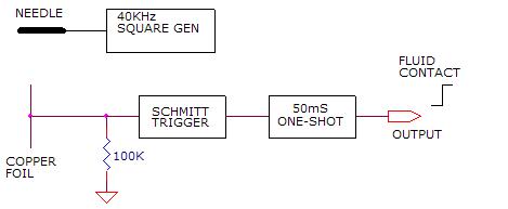
The circuit that Wily came up with is shown below.  A simple 40KHz 12v peak to peak square wave signal generator, using a 555 timer oscillator, was fed to the metal needle and the whole vertical indexing system, which was electrically isolated from everything else. 

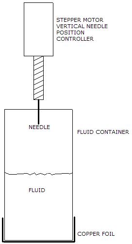
On the receiver end, a copper foil electrode, which was designed to fit snugly on the bottom of a plastic cup, acted as a holder for the fluid container. 

This electrode formed the other side of a capacitor plate.  When the need made physical contact with the fluid, the 40KHz signal was injected into the fluid.  The signal was then routed through the highly conductive fluid and would induce a similar 40KHz signal at the copper electrode, through capacitance coupling.  The copper plate electrode is connected to a simple receiver circuit.

The fast rise and fall times of the square wave signal produce narrow pulses at the receiver input.  A low power Schmitt trigger acts as a voltage comparator and converts the short pulses into logic pulses. The logic pulses are then connected to a retriggerable one-shot type circuit with a 50ms time constant.  The logic output of the one-shot is then fed to the system’s microprocessor. 

The result is a nice clean logic signal whenever the needle made contact with the fluid. The logic signal was used by the system’s computer to index the needle’s position, keeping just below the fluid surface.


The typical sequence starts with the vertical indexing system moving the needled to an upper most “home” position.  The system then moves the needle downward, using its stepper motor.  When the needle comes in contact with the fluid, the sensor circuit sends a logic signal to the computer.  The needle is then slowly indexed downward as the fluid is drawn off.

July 2010     Issue 11

Page 1 Back
Envelope
Circuit
Diagnosis
Experimenter's
Corner
Good Idea
gone Badly
New Products Rants &
Raves
What the World
needs Now
Wily Widget


Imagineering Ezine    Discover Solar Energy Dave Johnson & Associates Faraday Touch Switches


 About Us   |  Advertise on DiscoverCircuits.com   |   Report Broken Links  |    Link to DiscoverCircuits.com  |   
Privacy Policy


Discovercircuits.com endeavors to credit original designers.   Please alert us by eMail so we can
delete links to material that have been copied without your permission
.   Thank you.


© Copyright of all original material on this website is the property
of David A. Johnson, P.E. (Dave Johnson & Associates ) unless otherwise noted.  

Linking is ALLOWED but COPYING any content or graphics to your web site is EXPRESSLY PROHIBITED.
All material is provided "as is" without guarantees or warranty of any kind, either expressed or implied.