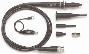
HOME Schematics Hobby Corner Dave's Circuits Electronic Resources Book Corner Contact Info


  Experimenter's Corner

  Previous Issues

X100 Scope Probe
By: Dave Johnson

These days, I seem to be designing a lot of circuits, which run on very low power.  Often the resistors being used in these circuits are in the multiple megaohm order of magnitude.  
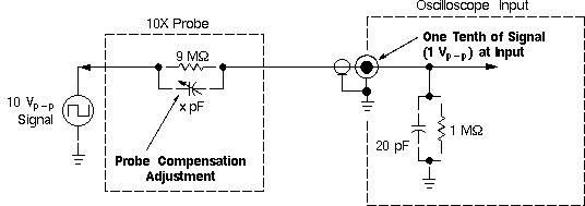
When looking at signals across such resistors, even the 10M load a typical X10 oscilloscope probe will produce large measurement errors and will influence the circuit operation.  To reduce the effect such a probe has on the circuit, I reach for my X100 scope probe.  My probe, with its 100M impedance, is a commercially made device but if you want to make one, it is not hard to do.


A typical oscilloscope probe circuit is shown below.  This classic model has a X1 and a X10 position.  In the X1 position, the signal collected at the tip goes straight into the 1M input of the scope.  In the X10 position the signal between the probe tip and the scope input is attenuated by factor of ten by including a 9M resistor between the probe tip and the scope input.  A trim capacitor in parallel with the 9M resistor is included and is adjusted to form a clean square wave on the scope screen, when the probe tip is connected to the 1KHz calibration signal, which many scopes provide.

To change the probe to a X100 device, the 9M resistor has to be changed to 100M.  The trim capacitor may also have to be changed but often the existing cap will work.
Adjust the trim capacitor for a clean square wave signal shown in (c) below"
Data sheet for a X100 scope probe.

http://www.tpi-thevalueleader.com/products/oscilloscopeProbes/TAW%20Differential%20Probes-0705.pdf


Please send comments to me


May 2010     Issue 9

Page 1 Back
Envelope
Circuit
Diagnosis
Experimenter's
Corner
Good Idea
gone Badly
New Products Rants &
Raves
What the World
needs Now
Wily Widget


Imagineering Ezine    Discover Solar Energy Dave Johnson & Associates Faraday Touch Switches


 About Us   |  Advertise on DiscoverCircuits.com   |   Report Broken Links  |    Link to DiscoverCircuits.com  |   
Privacy Policy


Discovercircuits.com endeavors to credit original designers.   Please alert us by eMail so we can
delete links to material that have been copied without your permission
.   Thank you.


© Copyright of all original material on this website is the property
of David A. Johnson, P.E. (Dave Johnson & Associates ) unless otherwise noted.  

Linking is ALLOWED but COPYING any content or graphics to your web site is EXPRESSLY PROHIBITED.
All material is provided "as is" without guarantees or warranty of any kind, either expressed or implied.