|
10Mhz to 20Mhz Light Receiver - Light power to volts conversion = APPROX.15mV per microwatt at 850nM. . . Circuit by David Johnson P.E.-July, 2006
10W HF Amplifier with KT907 - Schematic only, no circuit description __ Designed by © 2001YO5OFH, Csaba Gajdos
10W HF Linear Amplifier This project and your efforts will provide you with a 0.55 3 watt input to easily 10 watt output. The two linear amplifiers are ment for use with QRP SSB/CW/FM/AM transmitters on the amateur bands 15 and 17 meters can be powered from a 12 volt DC supply. The design is a good balance between output power, physical size. The completed amplifier will reward the builder with a clean, more powerful output signal for a QRP rig when radio conditions become marginal. It has a RF-sensing circuit (Q2) wich allows the amplifier to switch on automatically when transmitting. This project uses a "classic" RF transistor. MOSFET power amplifiers are discussed and build in the near future on this website. __ Designed by Guy Roels ON6MU
120VAC Under Voltage Tester - Using a cheap 24vac transformer, this circuit can test a product under low 95vac conditions. With the components show, it has a rating of 250 watts max.. . . Circuit by David Johnson P.E.-July, 2006
1296MHz high gain Amplifier - Schematic only, no circuit description __ Designed by © 2001YO5OFH, Csaba Gajdos
13cm power Amplifier - Schematic only, no circuit description __ Designed by © 2001YO5OFH, Csaba Gajdos
1Hz to 10kHz Voltage to Frequency Converter - JFET inputs with anti phase-reversal circuitry allow the LTC1055/56 to be used as a precision, ultra-high impedance comparator. The precision provides for very high linearity of the V/F generation while the high speed allows a large frequency range of operation. __ Linear Technology/Analog Devices App Note, Jun 21, 2011
1W HF QRP - Schematic only, no circuit description __ Designed by © 2001YO5OFH, Csaba Gajdos
2 Nanosecond, .1% Resolution Settling Time Measurement for Wideband Amplifiers - Linear Technology AN128 __ Designed by Jim WilliamsAug 16th, 2010
20Mhz VCSEL 3mw Laser Test Circuit - This circuit takes advantage of some new vertical cavity surface emitting lasers (VCSEL) that don’t require light output control circuits. The circuit shows how to drive the device from a single high speed CMOS
IC. . . Circuit by Dave Johnson P.E.-June, 2000
23cm 20W PA with M57762 - Schematic only, no circuit description __ Designed by © 2001YO5OFH, Csaba Gajdos
23cm 40W PA with M57762 - Schematic only, no circuit description __ Designed by © 2001YO5OFH, Csaba Gajdos
25W QRO with PL504 - Schematic only, no circuit description __ Designed by © 2001YO5OFH, Csaba Gajdos
27MHz toy car receiver - RF circuits are not easy to build. The purpose of this page is to make the circuit diagrams available for educational purposes. I won't be able to help you contructing them or give more info than what is written on this page. __ Designed by Peter Jakab
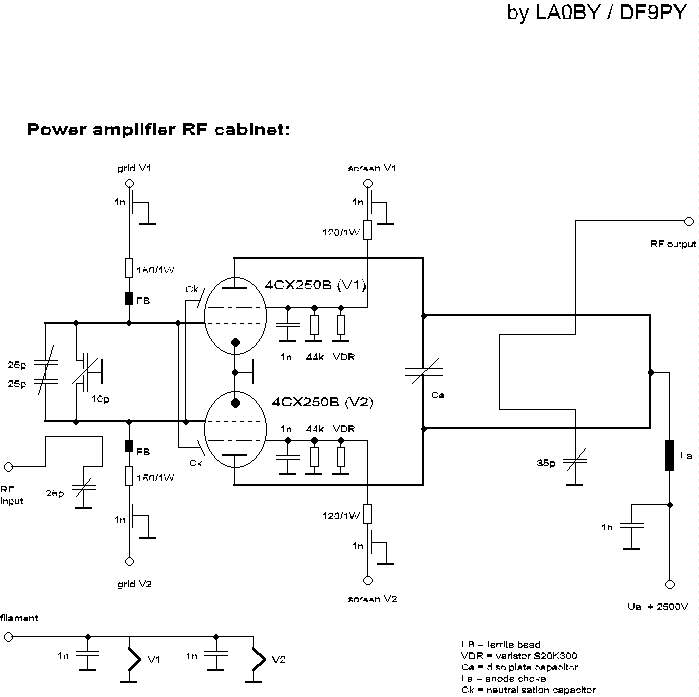
2m power Amplifier - Schematic only, no circuit description __ Designed by LA0 DF9PY
2Mhz Broad Band Optical Fiber Receiver - If you need more sensitivity than the above circuit this circuit provides about ten times more gain. It too is designed around an inexpensive plastic optical fiber detector . . . Hobby Circuit designed by David A. Johnson P.E.-June, 2000
3.3V Baseband Video Splitter/Cable Driver (DC Coupled) - A simple video splitter application using an LT6206. Both amplifiers are driven by the input signal and each is configured for a gain of two, one for driving each output cable. Here again careful input biasing is required (or a negative supply as suggested previously). __ Linear Technology/Analog Devices App Note, Mar 25th 2010
3.3V Single Supply LT6551 RGB Plus SYNC Cable Driver (DC Coupled) - The LT6551 drives four cables and operating from a single 3.3 V supply. The inputs need to have signals centered at 0.83V for best linearity. This application would be typical of standard-definition studio-environment signal distribution equipment (RGBS format). __ Linear Technology/Analog Devices App Note, Mar 25th 2010
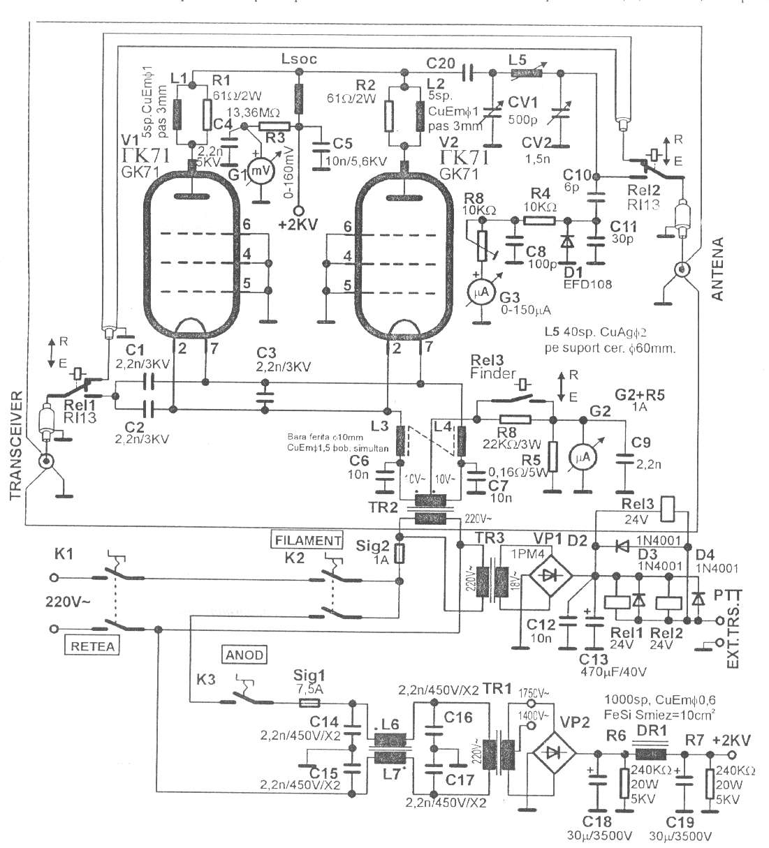
350W QRO with GK71 for 160-15m - Schematic only, no circuit description __ Designed by © 2001YO5OFH, Csaba Gajdos
3mw Laser Test-20Mhz VCSE - L - This circuit takes advantage of some new vertical cavity surface emitting lasers (VCSEL) that don’t require light output control circuits. The circuit shows how to drive the device from a single high speed CMOS
IC . . . Hobby Circuit designed by Dave Johnson P.E.-June, 2000
400MHz, 5V Single Supply Video Driver (AC Coupled) - The LT6557 400MHz triple video driver is specifically designed to operate in 5V single supply AC-coupled applications as shown. The input biasing circuitry is contained on-chip for minimal external component count. A single resistor programs the biasing level of all three channels. __ Linear Technology/Analog Devices App Note, Mar 25th 2010
432 MHz kilowatt Amplifier - Schematic only, no circuit description __ Designed by W1QWS
5 Watt HF CW transmitter - This is a very simple 5 watt CW TX based upon a TTL logic chip. There is just one "tricky" component and this is Cx. This component should have an impedance of about 1050 ohms at the frequency of interest. If you wish to reduce the transmitter power, increase the value of Cx. It is Cx which causes the square wave from the output transistor to approximate a sine waveform. The value of Cx is the price of simplicity in this TX __ Designed by Harry Lythall-SM0VPO
50/60Hz Sync Generator-Fully Isolated - This circuit will produce a single pulse at the zero voltage cross points of the power line voltage. An opto-coupler provides a very safe 5KV isolation. . . Circuit by David A. Johnson P.E.-December, 2004
500mW HF Linear Amplifier - his project was a particular surprise for me in that the BC547 (equiv 2N2222) can be used to build a 500mW linear amplifer covering the entire HF band with excelent spectral purity and no neutralising at all. Ugly-bug construction was used but I dare say that the good results are partly to do with the method of construction. __ Designed by Harry Lythall-SM0VPO
50Mhz Broad Band Optical Fiber Receiver Version A - If the above circuit it still too slow, you can try this circuit. What it lacks in sensitivity it makes up for in speed. The circuit attaches a plastic fiber optic PIN photodiode assembly to a small box containing a small 3v battery and a standard. . . Circuit by David Johnson P.E.-June, 2000
50MHz power Amplifier - Schematic only, no circuit description __ Designed by JH0WJF
5Mhz Broad Band Optical Fiber Receiver - This circuit is a simple broad band light detector that uses a very inexpensive IC and a PIN photodiode that is packaged for use with plastic optical fibers. It has a bandwidth from 1KHz to over 5MHz. It is great for experimenting with various modulated. . . Circuit by David A. Johnson P.E.-June, 2000
5W QRP with KT907 - Schematic only, no circuit description __ Designed by © 2001YO5OFH, Csaba Gajdos
700kHz, 1MΩ Single Supply Photodiode Amplifier - The measured output noise for this circuit was 153uVrms measured on a 1MHz bandwidth. Supply current was a low 2.2mA. __ Linear Technology/Analog Devices App Note, Mar 22, 2010
80m hexfet power Amplifier - Schematic only, no circuit description __ Designed by W7ZOI |