|
100W Guitar Amplifier - Guitar amplifiers are always an interesting challenge. The tone controls, gain and overload characteristics are very individual, and the ideal combination varies from one guitarist to the next, and from one guitar to the next. There is no amp that satisfies everyone's requirements, and this offering is not expected to be an exception __ Designed by Rod Elliott ESP
10W Amplifier using TDA2003 - Here is the circuit diagram of a 10W audio amplifier using the popular TDA2003 IC from SGS Thomson. The IC can easily deliver 10W to a 4 Ohms load at 18V DC supply voltage. The IC can be also operated from 12V and that makes it applicable in car audio systems
12 Volt powered, 4x15 Watt Audio Amplifier - Using car audio chips and intended for installation inside a computer. __ Designed by Manfred Mornhinweg
15dB UHF TV Antenna Booster - This is an UHF band TV antenna preamplifier circuit With 15dB gain to build easily. It is formed based on BF180 UHF Transistor. The first stage is an band pass filter constructed by the C1, CV1, L1, L4, C7 and C3, the second stage is a base-common
16 Watt Amplifier - This circuit provides 16 watts of amplification. it is built using two LM383 power audio amplifiers. use suitable heat sinks with the IC's. __ Designed by Andy Wilson
18W Audio Amplifier - High Quality very simple unit -- No need for a preamplifier __ Contact: IQ Technologies
2 Watt Amplifier - An audio amplifier made from discrete components with 2 Watts audio power into an 8 ohm load. Carlos has used this amplifier on his AM radio for many years. __ Designed by Carlos Feldman
2.3 GHz Power Amplifiers - Note: quality of text is poor. __ Designed by RL Campbell KK7B
2×100W Power Amplifier with STK4231II - Here the high power audio amplifier dual output at 100W max each output channel. Great output power with only using single chip.
2×25W Stereo Power Amplifier with STK4141II - Here the stereo power amplifier based on single IC STK4141II. This amplifier circuit will deliver 25W on each output channel.
2×30W Audio Amplifier with STK465 - Simple circuit with higher power output, this amplifier circuit is very easy to build. Just look at the PCB layout of this circuit. he active component required is just the main power amplifier chip STK465.
20 Watt Amplifier using LA4440 - This is the circuit diagram of a simple 19 watt amplifier using IC LA4440 from Sanyo. It uses very less components other than the IC LA4440. A very high quality circuit with respect to its cost and ideal for beginners.
20 Watt Class a Power Amplifier - A single-ended Class-A amplifier is essentially one where there is only one active driven output device. The passive "load" may be a resistor, an inductor (or transformer) oras in this amplifiera current sink. Of the three basic options, the current sink offers the highest linearity for the lowest cost, so is the ideal choice. Some esoteric (some might say idiosyncratic) designs use inductors or 1:1 transformers, but these are bulky and very expensive. Unless made to the utmost standards of construction, they will invariably have a negative effect on the sound quality, since the losses are frequency dependent and non-linear. __ Designed by Rod Elliott ESP
20 Watt GaAaFET Power on 2.3 GHz - Photocopypoor quality __ Designed by R. Berteismeier DJ9BV
20 Watt/ Channel Stereo Power Amplifier - Based on the versatile LM1875 from National Semiconductor __ Designed by Rod Elliott ESP
20 Watt/Channel Stereo Power Amplifier - Based on the versatile LM1875 from National Semiconductor __ Designed by Rod Elliott ESP
200W ATX PC Power Supply - This power supply has ATX design and 200W performance. I was drawed diagram, when I repaired this power supply. This power supply circuit uses chip TL494. Similar circuit is used in the most power supplies with output power about 200W
200W Audio Amplifier - Project available from Kemo Kits __ Contact: IQ Technologies
20dB VHF Amplifier - The amplifier is a circuit of high frequency RF with distinguishable materials. The amplifier as circuit strengthens the tendency of signal with concrete aid, depending on the frequency of signal. If the frequency of signal is included in the limits of spectrum of frequencies. __ Contact: IQ Technologies
20W Audio Amplifier - This schematic is designed to operate with minimum of external components. This amplifier offers high quality performance at very low distortion. Project is based on National LM1875 IC. The IC is thermal and short circuit protected. __ Designed by Rajkumar Sharma
20W Audio Amplifier using LM1875 - 20W Audio Amplifier kit is based on LM1875 IC __ Designed by Rajkumar Sharma
22 Watt Audio Amplifier - The 22 watt amp uses a TDA1554 two channel Audio Amp chip and is easy to build, and very inexpensive. The circuit can be used as a booster in a car audio system, an amp for satellite speakers in a surround sound or home theater system, or as an amp for computer speakers __ Designed by Aaron Cake
23 DB Bipolar DDS Amplifier - Some recent discussions with George Heron, N2APB and Craig Johnson, AA0ZZ regarding alternatives to using MMICs as amplifiers in DDS applications lead to the design of this 23 dB shunt feedback amplifier. This version is setup to operate at 12-13.8 volts, but with minor changes, can be made to operate with supply voltages as low as 5 volts. __ Designed by Jim Kortge, K8IQY
25 W Bridge Amplifier - A superb power amplifier using TDA 2009 which can deliver a blowing 25 W rms onto a 4 Ohm speaker and 13 W rms onto a 8 Ohm load. ICTDA 2009 is actually a 2 channel amplifier each of 13W rms on 4 Ohm.Here the two are connected in bridge format to double the output power to 25W.This circuit is designed exactly as what is said in the data sheet. __ Designed by
25 Watt MOSFET Audio Amplifier - High Quality simple unit. No need for a Preamplifier __ Contact: Flavio Dellepiane, fladello @ tin.it
2-9v battery-powered Amps based on the LM386. Schematic & PCB/perfboard layouts. - For better compatibility with effects driving the Little Gem, a FET buffer can be added. Both the Little Gem Mk II (seen below) and Ruby schematics include a simple buffer design. No further circuit modifications are necessary, however the input capacitor value of the amp may need to be adjusted to taste. __ Contact: holler @ runoffgroove.Com
2A3 Push-Pull Class a Stereo Amp - The input stage is comprised of a both halves of a 6SL7 octal dual hi-mu triode in a differential amp configuration with a 1ma constant current cathode load. I'm using field-effect (constant-current) diodes for simplicity. the diff amp approach was chosen for good power supply rejection, ease of balancing, good gain, and ease of application of *feedback*, if desired (hey, i like to keep an open mind). It also takes care of phase-splitting right up front. Note: I've returned the constant current diode cathode to -9V instead of ground in order to avoid the non-linearities about the pinch-off region (Vpo ~= 1.5V) __ Designed by Bob Danielak
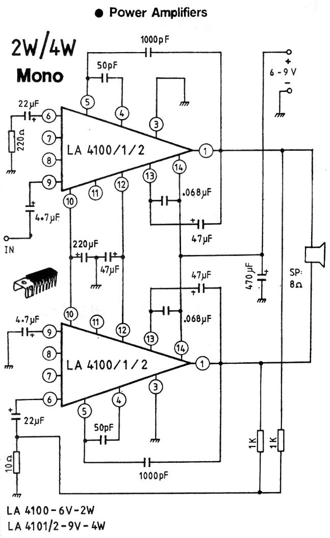
2W / 4W Audio Amplifier using paIR of LA4100, LA4101 or LA4102 Modules - Schematic only, no circuit description __ Designed by Petr Prause |