|
555 Bistable - Basic circuits and information about this timer/oscillator. Scroll to find Bistable Circuit __ Designed by Jose Pino
555 stepper pulse generator - The 555 Stepper Pulse Generator kit will help you with the pulse required to drive your favorite stepper Motor driver. This kit uses the populer 555 timer IC for generating the Stepping Pulse. it has two range low frequency and high frequency __ Designed by © 2008, Leiterplatten Zubehör und Reflow-Kit Beta LAYOUT
Accurate One Shot Pulse Generator - This timer circuit draws only 3ua of current, and can be powered by DC supplies ranging from 3v to 15v. The circuit produces accurate pulses whose time can easily be adjusted, based on the R1 x C1 time constant. The time should not change,. . . Circuit by David A. Johnson P.E.-September, 2010
Advertising Badge #1 with Flashing LED - I have seen numerous flashing light badges at trade shows and conventions. They are often handed out as gifts to promote some business. The devices often use inefficient circuits, which cause the battery power source to be quickly depleted. . . Circuit by Dave Johnson P.E.-March, 2002
Advertising Badge #2 with Flashing LED - This circuit uses a CD4013 dual D Flip/Flop IC. A single lithium battery will provide months of continuous LED flashing. It also has a tiny push-button switch to turn on and off the light flashing. . . Circuit by David Johnson P.E.-March, 2002
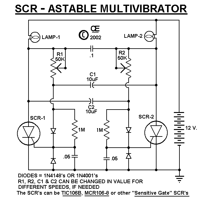
An SCR Flipflop for Alternating Flashing Light Bulbs - Schematic only __ Designed by G.L. Chemelec
Auto pulse generator senses & responds to a probed loA - D - 02/25/13 EDN-Design Ideas Use this handy pulse generator to inject momentary power pulses into a circuit under test. Design by Raju Baddi
Automatic Timeout included with this On/Off Flip/flop Circuit - This circuit is ideal when a device needs to be turned on and off with a single pushbutton switch, but also needs to turn itself off after some period of time. With the components shown, the output will stay on for only about 20 seconds . . . Hobby Circuit designed by David A. Johnson P.E.-May, 2012
Battery-Powered LED Flashing Advertising #2 - This circuit is similar to flashing LED advertising badge #1. It uses a CD4013 dual D Flip/Flop IC. The 74HCT74 IC in #81 does not always work. As in #81, a single lithium battery will provide months of continuous LED flashing. . . . Hobby Circuit designed by David Johnson P.E.-March, 2002
Bistable Flip flop - Here are two examples of bistable flip flops which can be toggled between states with a single push button. When the button is pressed, the capacitor connected to the base of the conducting transistor will charge to a slightly higher voltage. When the button is released, the same capacitor will discharge back to the previous voltage causing the transistor to turn off. The rising voltage at the collector of the transistor that is turning off causes the opposite transistor to turn on and the circuit remains in a stable state until the next time the button is pressed and released. __ Designed by
Bill Bowden
Build a Simple Circuit Complementary-Bracket-Pulse Generator - 20-Aug-09 EDN-Design Ideas When building push-pull switching power converters or motor controllers, you often need alternating pulses with a small amount of dead time between them to minimize simultaneous conduction in output-switching devices. Switching controller ICs have this feature, but they usually operate Design by Horst Koelzow, Global Thermoelectric, Calgary, AB, Canada
Build a UWB Pulse Generator On an FPGA - 06/23/11 EDN-Design Ideas Make pulses that reach twice an FPGA's clock frequency. You can implement a digital UWB (ultrawideband) pulse generator in most FPGAs. The design lets you create a pulsed signal with a frequency that’s twice the FPGA’s clock frequency (Figure 1). A previous design relies on asynchronous delays to make pulses of the desired frequency. That design, however, requires an FPGA that supports tristate pullups, such as the Xilinx Virtex 2 (Reference 1). Design by Punithavathi Duraiswamy, Xiao Li, Johan Bauwelinck, and Jan Vandewege, Ghent University, IMEC/Department of Information Technology, Ghent, Belgium
CD4093 Pulse Width Modulator - The IC used is a CMOS
type MC14093, a quad 2-input NAND Schmitt trigger. If you wish, it can be directly interchanged with the CMOS
MC14011 but this type is noisy. The speed is adjustable from 0-max. Max rpm is 2/3 the supply voltage __ Designed by Tony van Roon VA3AVR
Circuit Detects Current Pulse - 01/06/94 EDN-Design Ideas The pulse detector provIdeas a visible indication of positive and negative current pulses. The pulses amplitudes can vary from20 to150 mA. The pulses durations can range from10 to40 msec, and their repetition rate can span40 to180 pulses/minute Design by Richard McGillivray, Grey Bruce Regional Health Centre, Owen Sound, Ontario, Canada
Circuit Indicates Time to Dust - I have used the circuit below for many different applications, which require ultra low power drain. It uses a single CA4013 flip/flop. One section forms a pulse generator. The generator produces 100uS pulses at a rate of about 1 per second . . . Hobby Circuit designed by Dave Johnson P.E.-May, 2006
CMOS
Toggle Flip Flop using Laser Pointer - The circuit below uses a CMOS
dual D flip flop (CD4013) to toggle a relay or other load with a momentary push button. Several push buttons can be wired in parallel to control the relay from multiple locations. A high level from the push button is coupled to the set line through a small (0.1uF) capacitor. The high level from the Q output __ Designed by Bill Bowden
CMOS
Toggle Flip Flop using Push Button - The circuit below uses a CMOS
dual D flip flop (CD4013) to toggle a relay or other load with a momentary push button. Several push buttons can be wired in parallel to control the relay from multiple locations. A high level from the push button is coupled to the set line through a small (0.1uF) capacitor. The high level from the Q output __ Designed by Bill Bowden
DAC & flip-flops form constant-current-source - 23-Apr-09 EDN-Design Ideas Using two flip flops, you can program a serial-input DAC to produce a constant 4 mA Design by Marián Štofka, Slovak University of Technology, Bratislava, Slovakia
Delayed Pulse Generator - This circuit generates a short 10ms pulse 15 minutes after a “start” pushbutton switch is activated. . . Circuit by David A. Johnson P.E.-October, 2005
Descrete Set/Reset Flip Flop - Here are two examples of bistable flip flops which can be toggled between states with a single push button. When the button is pressed, the capacitor connected to the base of the conducting transistor will charge to a slightly higher voltage. When the button is released, the same capacitor will discharge back to the previous voltage causing the transistor to turn off. The rising voltage at the collector of the transistor that is turning off causes the opposite transistor to turn on and the circuit remains in a stable state until __ Designed by Bill Bowden
D-Flip/Flop One Shot Circuit - Yes you can use cheap D flip/flop logic circuits as nice one-shot pulse generators. This schematic shows how the popular CD4013 and the CD74HC74 can be used to generate pulses ranging from nanoseconds to seconds. . . Circuit by David A. Johnson P.E.-June, 2000
Discrete BiStable Flip Flop - Here are two examples of bistable flip flops which can be toggled between states with a single push button. When the button is pressed, the capacitor connected to the base of the conducting transistor will charge to a slightly higher voltage. When the button is released, the same capacitor will discharge back to the previous voltage causing the transistor to turn off. __ Designed by Bill Bowden
Discrete Set/Reset Flip Flop - Here are two examples of bistable flip flops which can be toggled between states with a single push button. When the button is pressed, the capacitor connected to the base of the conducting transistor will charge to a slightly higher voltage. When the button is released, the same capacitor will discharge back to the previous voltage causing the transistor to turn off. The rising voltage at the collector of the transistor that is turning off causes the opposite transistor to turn on and the circuit remains in a stable state until __ Designed by Bill Bowden
Dual Flip-Flop Forms Simple Circuit Delayed-Pulse Generator - 04/17/08 EDN-Design Ideas A delayed pulse generator provIdeas precision timing adjustments Design by Luca Bruno, ITIS Hensemberger Monza, Lissone, Italy
Dual Microphones Separate Voice From Noise - 06/23/94 EDN-Design Ideas The circuit in Fig 1 uses a pair of microphones to extract a voice from a noisy background. You must mount electret microphones X1 and X2 on the left and right sIdeas of the user's chest. Sound sources not equidistant from the microphones experience a phase shift. Because sound travels at 1120 ft/sec, the maximum phase shift for this design's/ Design by Samuel Kerem, Infrared Fiber Systems, Silver Spring, MD |
