Electronic Circuits and electronic circuits, electronic schematics plus an extensive resource for hobbyists, inventors and engineers

DiscoverCircuits.com, has 45,000+ electronic circuits, cross-referenced into 500+ categories.
We have searched the web to help you find quick solutions & design ideas.

Got Designs?
Please eMail
if you want me to link to and/or post your original design
NOTE:  We make every effort to link to original material posted by the designer. 
Please contact us if our link is not to your site!  Thanks.

DiscoverCircuits.com -- Hobby Corner
Last Updated on: Wednesday, June 02, 2021 04:02 AM

Hobby Circuits List

The contents & graphics of Discovercircuits.com are copyright protected.
LINK to Dave's circuit, but DO NOT COPY any files to your WEB SITE server


More  Alarm Circuits     Current Monitors   Testers

Clip-on AC Current Indicator Circuit
Pump Motor Monitor
For more details, see this design in Circuit Solutions Section

This circuit indicates when a pump motor is turned on.  It clips on the outside of the pump motor’s power cable and provides a transistor switch closure whenever the circuit detects current flowing to the motor.  The circuit draws so little current that a small lithium cell will power the circuit for years.

I chose to 
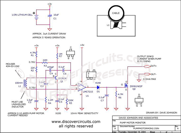
power the monitoring circuit with a small battery. With a simple battery supply, there is less a user has to worry about.  Using modern components, I was able to keep the current consumption to a very low level.  A small 3v lithium battery cell will power the circuit for about 5 years.  The two wires connected to the circuit’s transistor switch can be used to turn on a light or noise maker, located some distance from the monitoring box. 

The circuit uses a small unshielded 100mH inductor as a current transformer.  The voltage generated by the coil is fed to a single transistor circuit, which is configured as a high gain, low frequency Amplifier.  The circuit has a gain over 100.  The output of the Amplifier is connected to a voltage comparator.  The DC bias voltages at the input of the comparator set the sensitivity of the signal from the Amplifier at about 10 millivolts.  This should be sufficient for most applications.  If the coil is placed properly against the outside of the power cable, a current of 100ma AC should be sufficient to activate the circuit.  The output of the comparator is a pulse train equal to the 50Hz or 60Hz power line frequency.  A simple diode rectifies the pulses and produces sufficient DC voltage to turn on the transistor Q2.  The transistor acts as a switch, which closes when the circuit detects motor current flowing through the power cable.

If the user wishes to power an indicator light from the same 3 volt battery, he should use a flashing LED circuit, such as the one shown below.  This type of circuit will not tax a small battery.  Of course, the user can increase the battery size if desired.  The circuit will work fine from two 1.5 volt AA cells.


Click on Drawing Below to view PDF version of Schematic

More 

Hobby Circuits List
eMail David A. Johnson, P.E. about this circuit


HOME Schematics Index Hobby Corner Dave's Circuits Contact Info
Imagineering Ezine Dave Johnson & Associates Faraday Touch Switches


 About Us   |  Advertise on DiscoverCircuits.com   |   Report Broken Links  |    Link to DiscoverCircuits.com  |    Privacy Policy

Copyright  January, 1998 - June, 2021     David A. Johnson  All Rights reserved. 
 Linking is ALLOWED but COPYING any content or graphics to your web site is EXPRESSLY PROHIBITED.