|
DiscoverCircuits.com -- Hobby Corner
Last Updated on:
Wednesday, June 02, 2021 04:32 AM
Hobby Circuits List
The contents &
graphics of Discovercircuits.com are copyright protected.
LINK to Dave's circuit, but DO NOT COPY any files to your WEB
SITE server |
 |
|
|
|
|
|
|
More
Voltage Converters, Servo Circuits
|
|
Servo Pulse to
Voltage Converter
October 7, 2012
, Circuit designed by David A. Johnson, P.E. |
|
Servo Pulse to
Voltage Converter
A while back a Discover
Circuits visitor needed a way to convert servo pulses from a radio controlled device
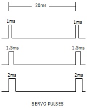
into a voltage. The drawing below, illustrates the pulse train of the received
signal. The time between pulses is a fixed 20ms while the pulse widths vary
from a low of 1ms to a high of 2ms.
The visitor wanted to convert the pulses
into a voltage such that a 1ms pulse width would produce 1 volt, a 1.5ms pulse would
produce 5v and 2ms pulse would produce an output of 9v. The circuit below
performs this conversion. |
|
|
The visitor wanted to
convert the pulses into a voltage such that a 1ms pulse width would produce 1
volt, a 1.5ms pulse would produce 5v and 2ms pulse would produce an output of 9v.
The circuit below performs this conversion.
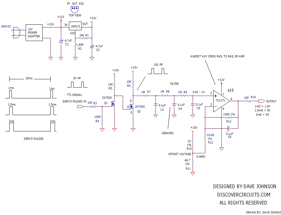
A
12 volt wall adapter is used to supply power to the circuit. A LM317 is used
to down regulate the voltage to 10v. The 0v to 5v TTL logic input pulses are first
converted into 0v to 10v swings. Those pulses are then sent through a three
stage filter network. The network averages the DC voltage, which is fed to
an operational Amplifier circuit. The circuit has a gain of 16 and a DC
offset voltage of 0.466v. The result is an output with the desired 1v to 9v
swing as the pulse widths vary from 1ms to 2ms. The response of the filter
network is not super fast, so there is a delay between a pulse width change and a
voltage change. The visitor did not think that the delay would be a problem. |
 |
|
|
|
Click on Circuit Below to view PDF of Schematic |
|
 |
|
|
|
|
|
|