|
13.8V 30-40A Power Supply - Schematic only, a powerful power supply for my amateur radio equipment using four HEX FET transistors for regulation. Text can be found at: http://www. Agurk.dk/bjarke/Projects/PowerSupplyFET/PowerSupplyFET.htm __ Designed by Bjarke Korsgaard 136 kHz Direct Conversion Receiver - The front end is described elsewhereprea136. htm - The scope is reduce as most as possible the image frequency. I have also tried a different front end, based on a low pass filter with frequency cut-off of 180 kHz. in my QTH I had a lot of undesirables signals on the screen of the PC. The filter is tuned with a signal generator for a bandwidth of 300 Hz, __ Designed by Claudio Pozzi, IK2PII
137 Khz Big Coil antenna, over 1 square meter - I like to use Atmel AVR Atmega PIC 16 PIC 16F876 PIC 16F84. Most electronics easy made for the novice and something is for the more experienced. __ Designed by Thomas Scherrer OZ2CPU
13cm power Amplifier - Schematic only, no circuit description __ Designed by © 2001 - YO5OFH, Csaba Gajdos
144MHz to 50MHz receiver converter - A simple accessory for a satellite station, that allows using a 6 meter capable radio in conjunction with a typical S-band to 2 meter converter. __ Designed by Manfred Mornhinweg
14MHz SSB 10mW Transceiver - I wanted to QRV on 14MHz SSB mode. One day when I walking on Akihabara city in Tokyo , while I have heard the sample transceiver on the ham shop , I have known that 14MHz can be used for domestic communication. They made Japanese domestic QSO about 14.18MHz. __ Designed by YO5OFH, Csaba Gajdos
15dB UHF TV Antenna Booster - This is an UHF band TV antenna preamplifier circuit With 15dB gain to build easily. it is formed based on BF180 UHF Transistor. The first stage is an band pass filter constructed by the C1, CV1, L1, L4, C7 and C3, the second stage is a base-common__
15M CW Transceiver Design - I've decided to design a new CW transceiver using some of the same design concepts employed in the highly successful 2N2/40 transceiver. The design goal of this rig is to provide a 15 meter CW rig that has good performance, while using discrete, readily available components whenever possible, including the venerable 2N2222 transistor, so that the rig can be reproduced in 3rd world countries by ham radio operators of modest means. __ Designed by Jim Kortge, K8IQY
16 Bit PC Serial Port Receiver CMOS
- This circuit was designed to control a 32 channel Christmas light show from the PC serial port. Originally designed with TTL logic, it has been simplified using CMOS
circuits to reduce component count. it is a fairly simple, reliable circuit that requires only 4 common CMOS
chips (for 8 outputs) , an optical isolator, and a few discrete components. __ Designed by Bill Bowden
160m mini portable End Fed Half Wave Tuner-MkII - A small portable 160m EFHW tuner design. This is the mini version of the previous version. The air core inductor is replaced with a toroid and the variable capacitor is replaced with a fixed capacitor combination. __ Designed by S.Spirat, Steph de VK5ZVS
1750 Meter Lowfer Band Amplitude Modulated RF - The 74HC4060 oscillates at 6.000 MHz, and is divided by 32 to get 187.5 kHz. Pin 5 of theCD4060 is a 732 Hz square wave which can be used to modulate the output stage rather than using a micro controller, but in this instance, the modulation __ Designed by Dick Cappels
1750Hz & 82.5Hz PiLoTtone generator with PIC12 IC - My Radio amateur callsign is OZ2CPU. I like to use Atmel AVR Atmega PIC 16 PIC 16F876 PIC 16F84. Most electronics easy made for the novice and something is for the more experienced. __ Designed by Thomas Scherrer OZ2CPU
175Khz Inductive Pulse Receiver - This circuit is discussed in more detail in the Experimenters Journal. The receiver’s six inch diameter coil detects the ring signal from the above transmitter and use a single NPN transistor to provided enough amplification for the signal to be easily viewed on an oscilloscope. . . Circuit by Dave Johnson P.E.-June, 2000
17M to 6M transveter - This transverter is based on my 6M receive converter. A 32MHz TTL oscillator is used as the local oscillator for both transmitting and receiving. RX/TX switching is handled by three SPDT relays. The first relay is used for switching the 18MHz input/output. The second relay is used as the 50MHz antenna relay. The third relay is used to switch the DC power supply. __ Designed by EI9GQ homebrew radio
18 DB LT1253 DDS Amplifier - This 18 dB gain amplifier was built Manhattan-style to evaluate the LT1253 dual video amplifier as a candidate output amplifier for DDS systems employing the Analog Devices AD9850 and similar devices. This dual amplifier was chosen to take advantage of its high gain-bandwidth product. By utilizing both amplifier sections, a very broadband (100 KHz to 30+ MHz) , high gain system could be built. __ Designed by Jim Kortge, K8IQY
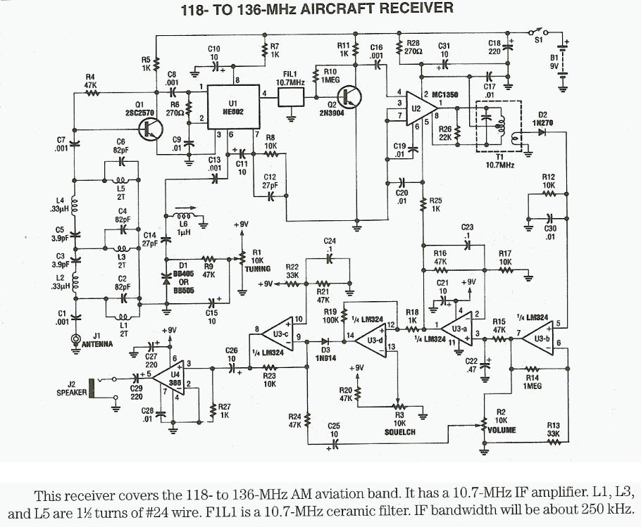
1-Chip Builds Tiny Aircraft Receiver - 09/25/97 EDN Design Ideas: it's easy to become bored spending time in airports. After all, you can do only so much work on a notebook computer with no reference material around. So, relax and have some fun at the airport--build the tiny, single-chip, aircraft-band radio in Design by Steve Hageman, Hewlett-Packard, Santa Rosa, CA
1GHZ Frequency Meter - This is 1GHz frequency counter with 100KHz resolution. Meter is built in around PIC 16F84A microcontroller and SAB6456 / U813BS prescaller __ Jan Kolar
1J6 Receiver - A battery operated one valve regenerative receiver using a 1J6 or 19 twin triode. Needs no external aerial in good signal areas __ Contact blehack @ yahoo dot com
1Khz to Over 70Mhz Light Receiver - This circuit uses one tiny C-MOS inverter IC to form a modulated light receiver with a very fast response. it is designed around a PIN photo diode that is packaged for use with plastic optical fibers. it can be used as an optical fiber receiver. By using the open end of the optical fiber it can "sniff" out any modulated light signals . . . Hobby Circuit designed by David Johnson P.E.-June, 2000
1-Transistor Amplifier/Detector - An amplifier may be added to boost the audio level as shown below. The current consumption of this amplifier is quite low and a power switch is not included. Disconnect the battery when the receiver is stored for long periods. __ Contact: Charles Wenzel of Wenzel Associates, Inc.
1us LED Pulse Driver + Voltage to Frequency Converter - This circuit receives the signal from the above amplifier and launches powerful 1uS infrared light pulses from a low cost LED that are frequency modulated by the audio information. The 10KHz center frequency of the pulse stream is low enough so a standard . . . Hobby Circuit designed by David A. Johnson P.E.-March, 1999
1W 10GHz Power Amplifier - We briefly describe here the 2-stages PA built to increase the power of the homebuilt transverter without impacting its originally compact design. __ Designed by Andrea IW9HJV and Johnny IW9ARO
1W HF QRP - Schematic only, no circuit description __ Designed by © 2001 - YO5OFH, Csaba Gajdos
1W Linear FM Booster - This RF Amplifier is used for boosting small fm transmiters and bugs. it use two Philips 2N4427 and its power is about 1Watt. At the output you can drive any linear with BGY133 or BLY87 and so on. its power supply has to give 500mA current at 12 Volts. More voltage can boost the distance but the transistors will be burned much earlier than usual. ! in any case do not exceed the 15Volts. The Amp offers 15 dB in the area of 80Mhz to 110 Mhz. L4, L5, and L6 are 5mm diameter air coils, 8 turns, with wire 1mm wire diameter. An easy project, with great results__ |