|
2 Transistor Amplifier - A 2 Watt audio amplifier made from discrete components. This was one of the earliest circuits that I ever designed and built, in Spring 1982. At that time I had only an analogue meter and a calculator to work with. Although not perfect, this amplifier does have a wide frequency response, low harmonic distortion about 3%, __ Designed by Andy Collison
2 Transistor LED Flasher - This 1.5 volt LED fasher runs more than a year on a single 'd" cell and alternately flashes 2 LEDs at about a 1 second rate. The circuit employs a 74HC14 CMOS
hex inverter that will operate at very low voltages (less than 1 volt). One section is used as a squarewave oscillator (pins 1 and 2) , while the others are wired to produce a short 10mS pulse on alternate edges of the square wave so the LEDs will alternate back and forth. The output sections each use a capacitor charge pump to increase the voltage for the LEDs __ Designed by Bill Bowden
2 Transistor Reflex Radio - Schematic & PC Board, no circuit description] __ Designed by © David Hoult
2 Watt Amplifier - A 2 Watt audio amplifier made from discrete components. This was one of the earliest circuits that I ever designed and built, in Spring 1982. At that time I had only an analogue meter and a calculator to work with. Although not perfect, this amplifier does have a wide frequency response, low harmonic distortion about 3%, __ Designed by Andy Collison
2 Watt Amplifier - An audio amplifier made from discrete components with 2 Watts audio power into an 8 ohm load. Carlos has used this amplifier on his AM radio for many years. __ Designed by Carlos Feldman
2 Watt Switching Power Supply - in this small switching power supply, a Schmitt trigger oscillator is used to drive a switching transistor that supplies current to a small inductor. Energy is stored in the inductor while the transistor is on, and released into the load circuit when the transistor switches off. The output voltage is dependent on the load resistance and is limited by a zener diode that stops the oscillator when the voltage reaches about 14 volts. Higher or lower voltages can be obtained by adjusting the voltage divider that feeds the zener diode. The efficiency is about 80% using a high Q inductor. __ Designed by Bill Bowden
20 Meter CW Transceiver - The 2N2/20 is the latest incarnation of the rather long list of 2N2/XX designs. Departures from the all "2N2222 transistor dictate" provided an opportunity to use a variety of discrete semicondutors to enhance performance. Within the iF chain, MPSH10 transistors were used, a J176 FET was used in the audio mute for very clean QSK keying, and a 2SC2166 final amplifier, used in the transmit strip allows the rig to put out about 7- watts. Commercial DBMs were also used to make construction easier for the beginning builder __ Designed by Jim Kortge, K8IQY
20 Watt Dummy load using SMD resistors - First 19 pcs 1watt 470 ohm SMD resistors is soldered on a 3mm thick cobber-bar; 470 / 19 = 24.7 Ohm.. on top of the first 19 resistors, 19 more is soldered; Now a 49.46 ohm resistor is made with good UHF behavior; Note the short leads to the BNC connector __ Designed by Thomas Scherrer OZ2CPU
20 Watt GaAaFET Power on 2.3 GHz - Photocopy - poor quality __ Designed by R. Berteismeier DJ9BV
20m SSB Transceiver, with DDS, PIC16, 10.7Mhz IF - My Radio amateur callsign is OZ2CPU. I like to use Atmel AVR Atmega PIC 16 PIC 16F876 PIC 16F84. Most electronics easy made for the novice and something is for the more experienced. __ Designed by Thomas Scherrer OZ2CPU
20W FM Amplifier - This Power amplifier is equiped with two Philips bipolar transistors : the BLV10 & BLW87. As lots of FM amplifier design, the RF transistors are in a class C bias. The FM amplifier has a 21 dB gain with a 55 to 65% efficiency. __
222 MHz Transverter - The original project was published in July'93 QEX magazine. Before starting construction, collect all the parts to complete the 3 boards in the design: circuit boards, semiconductors, and surface mount parts, wire for inductors, xtal, toroid form, etc. in addition you may want to consider a case, connectors, PA, or front end switching (you may not require it, depending on the radio you use for an iF - or can be done with almost any small 12v relay). You may also need to build a 3 resistor pad to reduce the Tx RF level from your transmitter __ Designed by Original Zack Lau W1VT, this project and supplemental notes Rick Bandla VE3CVG
23cm 20W PA with M57762 - Schematic only, no circuit description __ Designed by © 2001 - YO5OFH, Csaba Gajdos
23cm 40W PA with M57762 - Schematic only, no circuit description __ Designed by © 2001 - YO5OFH, Csaba Gajdos
2500 W PA controller with PIC16 - This display is serial controlled via 96 bits. The PA output power (up to 2500Watt) reflected power, current, voltage temperature and much more are displayed instantly also all data is transfered to a PC via the RS-232 port, the PIC 16 runs at 18Mhz performing 4.5MiPS. This kit is made by me, and is my programming model, all potentiometers serves as simulation for an analoque input. The 12 small LED simulates outputs that the PIC can controll, relays tube voltages and so on __ Designed by Thomas Scherrer OZ2CPU
25W QRO with PL504 - Schematic only, no circuit description __ Designed by © 2001 - YO5OFH, Csaba Gajdos
25W RF Amplifier - RF amplifier with 25W of power for 88-108MHz FM transmitters __ Designed by suthus55 @ hotmail.com
27 MHz FM Receiver - The FMR-201 is a crystal controlled single channel receiver, comprising of receiving, decoding and open collector output sections. __
27 MHz Receiver - This is a simple RF receiver mainly for low-distance digital radio receiver application. The analog output of this circuit should be connected to a schmitt-trigger signal conditioning circuit with a proper value capacitor (from collector of T3). L1 for 27Mhz is about 10 turns, 6 mm diameter coil body. __
27MHz toy car receiver - RF circuits are not easy to build. The purpose of this page is to make the circuit diagrams available for educational purposes. I won't be able to help you contructing them or give more info than what is written on this page. __ Designed by Peter Jakab
27MHz/ 49 MHz Walkie Talkie - Lots of people are requesting walkie-talkie and RF remote control schematics, so here is some. Building these circuits needs special equipment and expertise in RF circuits. if you are going to experiment with these circuits, please __ Designed by Peter Jakab
2m (144MHz) Dual Gate FET Low Noise Amplifier - My good old FT-290 2m SSB and FM radio, had about 1uV sensitivity before installing this amp.
Now it is 150nV just like the best radios I have tested. Stations I could hear with noise, are now loud and clear ! ! __ Designed by Thomas Scherrer OZ2CPU
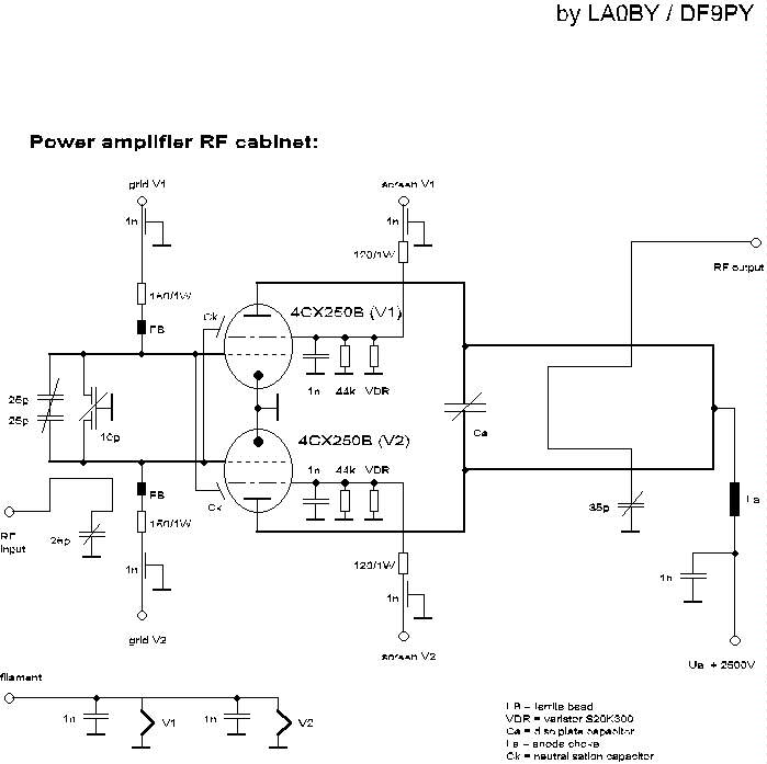
2m power Amplifier - Schematic only, no circuit description __ Designed by LA0 DF9PY
2m-20m Transverter - This little circuit is a transmitting and receiving converter (transverter) that converts a FT290 or similar multimode handheld transciever to the 14MHz amateur band. The project is a single board module that needs an external local oscillator, for example, the VHF harmonic oscillator (or QRP VHF FM TX) LO for transverter project. it should be a relatively simple matter of scaling coils __ Designed by Harry Lythall-SM0VPO
2Mhz Broad Band Optical Fiber Receiver - if you need more sensitivity than the above circuit this circuit provides about ten times more gain. it too is designed around an inexpensive plastic optical fiber detector . . . Hobby Circuit designed by David A. Johnson P.E.-June, 2000
2-Transistor Amplifier - it has been interesting analyzing these radios. You have to give the Japanese credit for even making a radio that can drive a speaker with only 2 transistors! Basically, the first transistor (Q1) performs double-duty. it first acts as an RF amplifier, with some of the signal being fed back to the antenna coil to provide some regeneration for better selectivity and sensitivity __ Designed by schematic and circuit description were provided Ronald Rissel
2-transistor Radio - Here is a simple radio that was designed to minimize unusual parts; there isn't even a detector diode! The sensitivity isn't as high as the one-transistor reflex but the simplicity is attractive. Strong stations will provide plenty of volume __ Contact: Charles Wenzel of Wenzel Associates, Inc.
2uS Light Pulse Receiver - Although the LF357 is an obsolete part, this circuit gives you an idea how to build a sensitive modulated light detector with high ambient light immunity. The first section uses a 100mH inductor as an efficient photodiode current to voltage conversion circuit. . . Circuit by David A. Johnson P.E.-June, 2002
|