|
300/1200 baud BAYCOM MODEM (revision and improved) - Ham Radio - Modems and Soundcard interfaces __ Designed by Guy Roels ON6MU 30Khz Light Receiver Amp - This circuit uses NPN darlington transistor to amplify the signal produced from short light flashes, as detected by a PIN photo diode. The circuit draws only about 330uA from a 6v battery. . . Circuit by Dave Johnson P.E.-March, 2002
30M Direct Conversion Receiver Project - A lot can be learned when using strict design criteria to build a project. I set out to build an entire receiver using only 2N3904 transistors and at the end settled upon the design shown above. This design resembles that of the Ugly Direct receiver on this web site in a lot of ways and is also a low-cost popcorn project. __ Designed by Todd, VE7BPO
30m QRSS Receiver - The inspiration for this project was Paolo iZ1KXQ, who used a simple SA602-based Homebrew direct conversion receiver to produce some very nice QRSS reception reports, of my Junkbox QRSS beacon and others. Paolo's receiver was based on a 1997 QST article by Daniel Wissell, N1YBT: "The 40m SLR - a Shielded-Loop Receiver". Paolo didn't use a shielded loop, he used a toroid as matching and input filter connected directly to a 30m dipole. __ Designed by Hans Summers
30W VHF FM Amplifier for 88-108 MHz with BLF245 MOSFET - The achievement of this 30-watt amplifier has been designed to take place on a heatsink microprocessor PC equipped with its fans, the advantage of this method of cooling has been selected for the fact that (French __
32 Bit Serial Receiver - This is the schematic for an FM transmitter (57.6 K Baud TTL & CMOS
) with 3 to 3.5 W output power that can be used between 90 and 110 MHz. Although the stability isn't so bad, a PLL can be used on this circuit. __ Designed by Bill Bowden
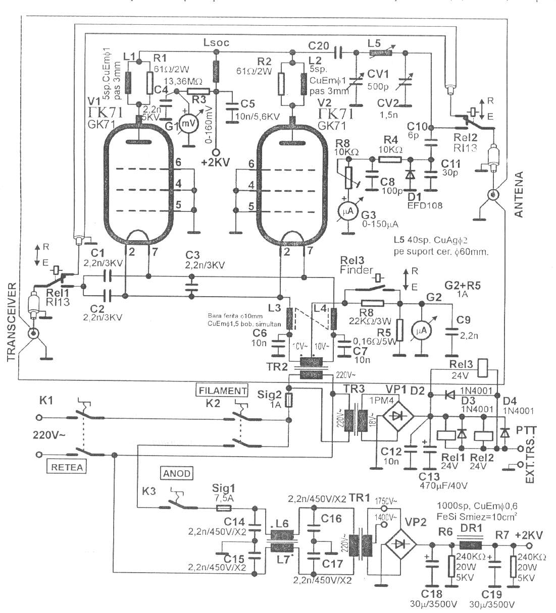
350W QRO with GK71 for 160-15m - Schematic only, no circuit description __ Designed by © 2001 - YO5OFH, Csaba Gajdos
3-Channel UHF Rolling-Code Remote Control, Pt.1 - This high-security 3-button UHF transmitter and receiver can be used for keyless entry into homes and commercial premises and for controlling garage doors and external lighting. Three separate outputs on the receiver can be used to activate various electrical devices such as a door strike, a motorised garage door and 230VAC lights. Up to 16 transmitters can be used with the one receiver so it's even suitable for a small business.__ SiliconChip
3cm SSB transverter - We describe here one of the two 10GHz SSB transverters we built around pieces of LNBs for satTV. Converts 3cm ham band from/to 432MHz iF, has 1W TX power and its Local Oscillator can be locked either to an internal OCXO or to an external frequency standard. __ Designed by Andrea IW9HJV and Johnny IW9ARO
4 Band Double Tuned Preselector - The circuit requires an RF input which can be from a longwire or a loop antenna. The Preamplifier has a range from 550kHz (Medium Wave) up to 30 MHz in the SW band. The input Switch S1, applies voltage to a set of relays which switch in the appropriate coils __ Designed by David Sayles
4 channel 433MHz remote control transmitter / receiver based on SM5162 & SM5172 chips - The radio control uses pre-calibrated 433 MHz transmitter and receiver modules. The SM 5162 presents a code to the transmitter module depending on the status of the input switches. The 555 is configured to provide a regular pulse to the 'transmit enable' (pin 15) of the SM 5162 - this pulse runs at a frequency of about 7 Hz (the LED will flash with each transmission). This means that the transmitter will update the code transmitted 7 times a second. __ CdS Electronic
4 channels RF wireless transmitter and receiver - This is a very simple Wireless RF transmitter circuit that consists of the Holtek HT-12E encoder chip and AM 418MHZ-transmitter module (WZ-X01, other similar device can be used). Using the hybrid RF xmit/receive modules make building the RF remote control a lot easy __ Contact info @ wzmicro.com
4 MHz Amplitude Modulated RF Source - A while back I needed an amplitude modulated signal source at 4 MHz. This circuit was literally thrown together with parts laying on the bench. I built it dead bug style on a piece of copper clad board. it should work with little or no modification, other thano get it to oscillate, and at higher frequencies, you might have to reduce the capacitor values a little. Just be __ Designed by Dick Cappels
4 Transistor FM Receiver - This is a pocket sized receiver I built in 1994. The idea was to make a simple but useable receiver running off 3V. My previous 6 transistor receiver was more bulky, requiring 12V. This meant 10 x AA cells. I designed and made a PCB, . __ Contact blehack @ yahoo dot com
40 Meter Direct Conversion Receiver - Using the circuit of direct-conversion receiver described here, one can listen to amateur radio QSO signals in CW as well as in SSB mode in the 40-metreband. The circuit makes use. __
40 Meter Popcorn Superhet Receiver - schematic for a no-frills, relatively low-cost CW superhet receiver with a 4.00 MHz intermediate frequency. There is no AGC or RF gain control, however this receiver has good large signal handling capability. This receiver uses just 6 bipolar transistors and an op amp for reasonable volume into headphones. Much __ Designed by VE7BPO
40 Segment LED S-Meter - Provide your radio with a very string signal, then adjust the HiGH LEVEL pot to the threshold of illuminating the last LED (all LEDs on). Remove the signal completely, then adjust the LOW LEVEL pot to the threshold of no LEDs illuminated. if your radio's S-meter output is greater than 5 volts, you mau wish to replace the HiGH LEVEL pot with a 10K resistor, and provide pin 6 of the right-most 3914 with the cathode of a 6.1 volt zener diode, pulled up to 13 volts with a 1K resistor. The anode should be connected to ground. You may use a higher voltage zener if necessary. __ Designed by N6ZAV Marty Mitchell
40 to 6 Meter "No Tune" Transverter - This project is a 40 meter to 6 meter CW "no tune" transverter using ten 2N2222 transistors and one 2N2907. The transverter requires 2 watts of drive from a 40 meter cw transceiver and outputs 2 watts on 6 meters. On receive, it uses the 40 meter rig as the intermediate frequency amplifier. its receive sensitivity is approximately 0.5 microvolts. Transmit spurious outputs are less than -50 dBc, meeting FCC spectral purity at a 2 watt power level. All transmit/receive switching is solid state. __ Designed by Jim Kortge, K8IQY
40/20 trap dipole - Portable 40/20 trap dipole - Here's an easy to make trap dipole for 40 and 20 meters. I made this for portable operations, mostly for "to the field" type QRP contests. Being able to switch bands between 20 and 40 quickly and without re-adjusting an antenna tuner is a nice feature. The only problem is it's a little heavy with the feed line and all, and putting it up in the raw New England woods can be daunting. __ Designed by Steven "Melt Solder" Weber KD1JV
40Khz Light Receiver Amp - This circuit is similar to 30KHZ LIGHT RECEIVER AMP but provides more gain and operates up to 40KHz. However it draws more power supply current.. . . Circuit by David Johnson P.E.-March, 2002
40khz TV-VCR Light Source Repeater - This circuit is designed to be placed directly in front of a standard TV or VCR remote. The exiting light pulses produced by the circuit match the pulses from the remote but are about 10 times more powerful. Using the device, the remote can operate a TV or VCR over three times the normal distance. . . Circuit by David A. Johnson P.E.-June, 2000
40Khz Ultrasound Receiver - A X100 transistor amplifier is followed by a zero cross detector circuit, using a voltage comparator. The output is a TTL logic signal, corresponding to the received 40KHz signal. . . Circuit by David Johnson P.E.-January, 2006
40m Direct Conversion Receiver - Building a practical and usable direct conversion receiver for the 40 m CW band is not as simple as it might appear. Broadcast station signals from the adjacent 41 m band, will easily overload most direct conversion mixer designs with their unwanted__
40-Metre Direct Conversation Receiver - Using the circuit of direct-conversion receiver described here, one can listen to amateur radio QSO signals in CW as well as in SSB mode in the 40-metre band. The circuit makes use...__ Electronics Projects for You
42 Mc Band to 88 Mc Band retrofit Converter Project - Before World War ii the FM radio band was just below 50 Mc. Read all about it. if you have such a radio, you might want to build this converter. it will let your old set receive. __ Designed by Andrew R. Mitz
432 MHz kilowatt Amplifier - Schematic only, no circuit description __ Designed by W1QWS
450-2000KHz AM receiver (ZN414, MK484, TA7642) - Ham Radio - V-U) HF AMPLiFiER - Schematic __ Designed by Guy Roels ON6MU
450MHz-800MHz UHF Preamplifier - This circuit is designed to work at UHF frequencies in the range 450-800MHz. it has a gain of around 10dB and is suitable for boosting weak TV signals __ Designed by Andy Collison
455 Khz MF to AF converter used for DRM reception in a Yaesu FRG-100 receiver - Ham Radio - V-U) HF AMPLiFiER -This is a very sensitive homemade MF converter/interface allowing you to receive the DRM radio (Digital Radio Mondiale) with your general coverage receiver and a soundcard. it can also be used for software radio apllications, and other MF to LF experiments (not just DRM, and surely not just for the Yaesu FRG-100) ! __ Designed by Guy Roels ON6MU
45-860MHz Radio receiver Based on UV916-tuner - This receiver use a TV-tuner, a simple radio-circuit and a interface to a computer. computer control (set) receiving frequency from 45-860MHz. purpose of this project is to learn about tuners, it's a pre-project for my Spectrum analyzer project. UV916 or UV918 tuner is easy to find in broke TV or VCR:s. it is a common tuner __ Contact maxit91 @ hotmail.com
49MHz Walkie Talkie - Lots of people are requesting walkie-talkie and RF remote control schematics, so here is some. Building se circuits needs special equipment and expertise in RF circuits. if you are going to experiment with se circuits, please note that I did not build __ Designed by Peter Jakab, Electrical Engineer, Engineer of Informatics
4Mbps IRD Receiver in MS8 & SO-8 Package LT1328 - DN152 Design Notes__ Linear Technology/Analog Devices
4-Watt AF Amplifer - i have recently included a page about AF amplifers for use with Homebrew rigs. in this I mentioned that I may include a practical one-watt circuit, complete with PCB foil and layout. Here it is, but I have taken the liberty of engineering it to provide 4-watts of AF output and with a frequency response almost suitable for Hi-Fi applications __ Designed by Harry Lythall-SM0VPO |