|
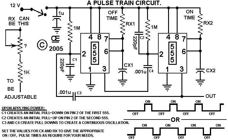
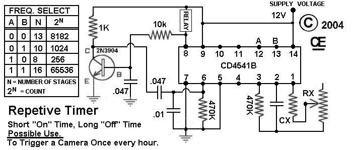
Timer that has a 50% duty Cycle - Here is a basic circuit using a dip switch to control all the variables of this IC . it has a Delay of a Number of Seconds, as Determined by You. Then it output goes Hot for a number of seconds, Then the Delay again, Hot Again, AND REPEATiNG. Optionally, instead of using the switch, you can take off wires to additional logic circuits. __ Designed by G.L. Chemelec Timer that is Useful for Repetitive Triggering - it has a Delay of a Number of Seconds, as Determined by You. Then it output goes Hot. A Mosfet can be Added as shown to drive more Current. Useful Examples of this circuit: Flashing a Camera for sequential time shots. Or turning on a Sprinkler every 24 hours. __ Designed by G.L. Chemelec
Timer warns when pills are due - 05/10/01 EDN Design Ideas: Some people need to take medication at precise, regular intervals. When you're in a hospital, a medical staff is present to ensure that you take your medication on time. But when you're taking medication at home, you must frequently look at the clock-a clear annoyance. When my wife was pregnant, she needed to take medication every two hours from 8 am to 10 pm. To help her time the two-hour intervals, I built the battery-powered circuit in Figure 1. The circuit derives its power from a 9V PP3 battery. All the ICs are CMOS
-based; the low power consumption of the circuit allows one-week autonomy. When you press the start button, BP1, a two-hour delay commences. Design by J Terrade
Timer with 555 - Some useful circuits using the LM555 IC . Scroll to find the Timer with 555 circuit __ Designed by Jose Pino
Timer with Alarm - This simple alarm timer circuit is made with 4060 which has an integrated oscillator with a good stability with a relatively wide frequency range. in the circuit diagram the oscillator frequency is set by the RC network that is connected at pins 9, 10 and 11. When the timer with alarm circuit is connected with S1, the pulse __ Designed by Popescu Marian
Timer with Musical Alarm - This low-cost timer can be used for introducing a delay of one minute to two hours. After the timing period is over, a musical song is heard. The circuit is built around...__ Electronics Projects for You
Timers Collection - Did you know there are at least 6 different kinds of timers? This circuit implements all of them! With our complete PCB design, you can build yourself an universal module, compelte with power regulator. __ Designed by Projects & Ideas from Nutchip.com
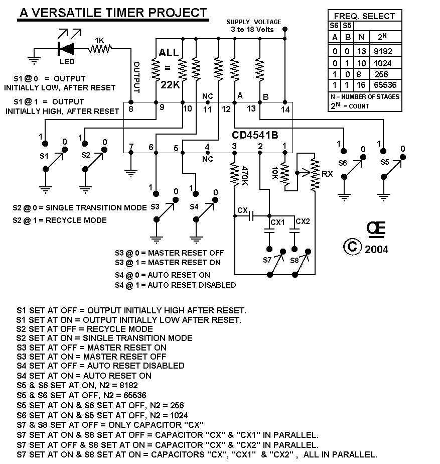
Timers for Very Long Delays using a CD4 541B - Very Useful Timers __ Designed by G.L. Chemelec
Timers Generate Variable-Sweep Frequencies - 08/01/96 EDN Design Ideas: The circuit inFigure 1 generates a 4- to 5-kHz output frequency that precisely sweeps a variable amount of 1 to 100 Hz over a variable time of 0.5 to 5.0 sec (1000-to-1 rate range). The resolution is 1 Hz, and worst-case accuracy during the sweep is 3 Hz (0.06%). This circuit was designed to run from an 8-bit PC iSA bus, but any µC with an 8-bit bus and the appropriate control signals can control the circuit. Design by D Hayden, Hayden Electronics Design, San Diego, CA
Timers with 4060B - Build a reliable timer to switch devices on and off - from 30 seconds to 24 hours. __ Designed by REUK-Renewable Energy UK website
Tiny Timer - Developing a lighting control unit recently, the author found that available analogue or mechanical timers were not sufficiently accurate or convenient. Without further ado he developed a timer switch driven by a small AVR controller of the type ATtiny2313must register on this site __ Designed by Published in Elecktor July/Aug, 2010
Token Passing Fits Large Counters Into CPLDs - 05/11/95 EDN Design Ideas: Fitting a large, loadable counter into a complex PLD (CPLD) while operating at the device's maximum frequency requires a few tricks. Fig 1 shows a 40-bit, loadable counter with a terminal-count output. The problem with fitting this design into a CPLD is that the design exceeds the usual number of logic-block inputs, which is 36 or fewer. Normally, for the most significant bit Fitting a large, loadable counter into a complex PLD (CPLD) while operating at the device's maximum frequency requires a few tricks. Fig 1 shows a 40-bit, loadable counter with a terminal-count output. The problem with fitting this design into a CPLD is that the design exceeds the usual number of logic-block inputs, which is 36 or fewer. Normally, for the most significant bit Design by Chris Jones and David Johnson, Cypress Semiconductor Corp, San Jose, CA
Touch Controlled Mute Switch with 555 IC - Here is another simple circuit to mute the volume of Audio devices through simple touch. it exploits the action of the flip-flops in the timer IC 555 to reduce the volume of the Audio amplifier. IC NE555 is designed in the toggle mode. its lower and upper comparator inputs are connected to the touch plates which can be __ Designed by D Mohankumar
Touch Sensor Switch with 555 timer - This is a very simple touch sensor switch that is build with the 555 timer IC . You just need to touch the metal plate and the relay gets energised and is kept in this state for about 100 seconds, then is released. This kind of sensor switch is suitable for making touch operated bells, buzzers of small toys which operate for a __ Designed by Popescu Marian
Touch Switch - The Touch Switch circuit will detect stray voltages produced by mains voltages and electrostatic build-up in a room. in the first circuit, pin 2 must see a LOW for the circuit to activate. if sufficient static voltage is detected by the plate, the chip will change state. if not, you will need to touch the plate and the 0v rail__ 555-Timer
Touch-Free Timer Switch - This type of infrared proximity circuit is widely used as an electric switch where physical contact is not desired for hygiene purpose. For example, we commonly see use of infrared proximity...__ Electronics Projects for You
Toy Organ - This circuit produces a tone according to the button being pressed. Only 1 button can be pressed at a time, that's why it is called a monophonic organ. You can change the 1k resistors to produce a more-accurate scale. __ 555-Timer
Traffic Light - This project operates red, amber and green LEDs in the correct sequence for a single UK traffic light. The time taken for the complete red, red & amber, green, amber sequence can be varied from about 7s to about 2˝ minutes. A 4017 counter is used to produce the traffic light sequence and this project could be adapted __ Designed by John Hewes
Traffic Lights - Here's a clever circuit using two 555's to produce a set of traffic lights for a model layout. The animation shows the lighting sequence and this follows the Australian-standard. The red LED has an equal on-off period and when it is off, the first 555 delivers power to the second 555__ 555-Timer
Traffic Lights-4 Way - This circuit produces traffic lights for a "4-way" intersection. The seemingly complex wiring to illuminate the lights is shown to be very simple, in this diagram. __ 555-Timer
Trangular wave generator - Different wave generator circuit is used troubleshoot electronics circuit. We have already published different type of wave generator. Now, Here is a circuit of advanced triangular wave generator for generating triangular wave with maximum peak level (VMAX) and minimum peak level (VMiN) in order to overcome the limitation of changing frequency with changing frequency with change in the value of generated waves.__
Transcendent Frequency Counter - This is a top quality project designed to obtain maximum performance. The hardware and software has been pushed to reach the frontier of technology. The transcendent is not only a frequency counter, it is a corner stone in your successfully constructions. __
Transistor Tester - The 555 operates at 2Hz. Output pin 3 drives the circuit with a positive then zero voltage. The other end of the circuit is connected to a voltage divider with the mid-point at approx 4.5v. __ 555-Timer
Transistors offer overload Delay - 16-Sep-04 EDN Design Ideas: Although an SMPS (switch-mode power supply] can protect itself against permanent short circuits, it sometimes has problems when dealing with transient overloads. Transient overloads are not short circuits but can push the power supply above its nominal load value. This scenario occurs with typical loads such as printer heads and small motors Design by Christophe Basso, On Semiconductor, Toulouse, France
Transition Counter Gauges Thermal Stability - 01/04/96 EDN Design Ideas: The transition count of Figure 1is an easy way to determine if the temperature in a heater is stable. The stable state maximizes the transitions. This circuit works like a digital filter with controlled frequencies and is simpler than many other analog- and digital-circuit alternatives Design by Jose Luis Arce, Tecnosuma Havana, Cuba
Travel Alarm used to control 250 milliwatt transmitter. - The timer consists of a Radio Shack travel alarm. I disconnected the pizeo-ceramic beeper and used the signal to set a flip-flop built from a CMOS
4011. The output of the flip flop is connected to a switching transistor which supplies voltage to the CW iD. I used an R/C combination on the flip/flop so it would be reset when first powered up. A push button is provided so the flip/flop can be set manually (turning on the transmitter) __ Contact Joe Leggio WB2HOL
Triangle / Square wave generator - Transistor Q1, a 2N3563, and its associated components form an oscillator circuit that will oscillate if, and only if, a good crystal is connected to the test clips. The output from the oscillator is then rectified by the 1N4148 signal diode and filtered by C3, a 100pF capacitor. __ Designed by Izhar Fareed
Trimming the Internal Clock on a KX8 Microcontroller - Example algorithms for manually or automatically tuning the oscillator on the internal clock generator of the popular MC68HC908KX8 microcontroller. Also includes batch test results and a video. __ Contact David Cook
TV based Receiver for a Standard Frequency Generator - Schematic Only__
TV Remote Control Jammer - This circuit confuses the infra-red receiver in a TV. it produces a constant signal that interferes with the signal from a remote control and prevents the TV detecting a channel-change or any other command. This allows you to watch your own program without anyone changing the channel__ 555-Timer
Two CMOS
Based 24-Hour Timers - Timer Circuits: A pair of multi-range timers offering periods of up to 24 hours and beyond. Both are essentially the same. The main difference is, that when the time runs out, Version 1 energizes the relay and Version 2 de-energizes it. The first uses less power while the timer is running; and the second uses less power after the timer stops. Pick the one that best suits your application. __ Designed by Ron J.
Two nixie display clock - My clock building habit is apparently as bad as ever. This time, it was inspired by a stash of Burroughs B5092s, so I needed to vertically align it. Also, since I wanted to make it as small as possible, I wanted to keep nearly everything surface mount, so I abandoned the idea of using 74141s in favor of standard BCD to decimal converters plus some external drive transistors. No need to multiplex since i'm only using two tubes, so this design is actually pretty straightforward. __ Designed by © 2007 Riad S. Wahby
Two Tone Generator - This two-tone generator includes 3 ICs NE555 Astable Multivibrators. You can vary the duration of each tone by changing the 10k resistor or 100MF capacitor at IC 1 or changing resistors and capacitors at IC 1/2 for higher or lower tone. __ Designed by Andrew R. Morris
Two transistor 40 milliwatt fox transmitter - This two transistor 144 MHz transmitter uses a 48 MHz scanner crystal as an oscillator / tripler. A second transistor boosts the power output to 40 milliwatts. A 7-element filter is used to minimize output on the third harmonic. (I did not want it to be easy to RDF this on the 450 MHz third harmonic) __ Contact Joe Leggio WB2HOL
Two Transistor Atomic Frequency Standard - Pretty ambitious title, wouldn't you say? Well, follow the reasoning: if you lower the voltage on the two-transistor flasher to 1.5 volts, the loop gain drops too low for sustained flashing. (See the circuit below.) But, the circuit is highly regenerative and only needs a very tiny push to get it going. By adding a short wire, only a few inches, to the PNP base, the circuit will be triggered into oscillation by the AC electric field from the electrical power (50 or 60 Hz in most places) __ Contact: Charles Wenzel of Wenzel Associates, Inc.
Two Transistor Oscillators - This page has two unusual two-transistor oscillators. I set the component values for a low frequency application. Both circuits draw only about 1 micro amp of current. . . Circuit by David A. Johnson P.E.-December, 2002
Two-Tone Audio Generator-M0DGQ - Schematic only __ Designed by va3iul
Two-tone doorbell using 555 timer - No circuit description, schematic only__ CdS Electronic
Two-Transistor Low Power Oscillators - This page has two unusual two-transistor oscillators. I set the component values for a low frequency application. Both circuits draw only about 1 micro amp of current . . . Hobby Circuit designed by Dave Johnson P.E.-December, 2002 |