|

|
|
|
|
|
|
|
|
Power Supply Problems
Excessive +5v Supply
Current Drain |
 |
I was troubleshooting a circuit board the other day, which had a +5v power
supply problem. I thought I would walk you through some of my techniques for
tracking down power supply problems. Circuit boards with power supply problems are
quite common, mostly due to the number of parts that are touched by a DC supply.
The board I was fixing was part of a complex video processing circuit I
designed some 15 years ago. One of my old clients had collected about 10 of the old
boards and needed them tested and repaired. |
|
The note attached to one of the boards sent by my client just said, “no
video.” I could tell there was a problem somewhere on the supply since the 5 volt
regulator was getting fairly warm. It was still cranking out 5 volts but it was
certainly under more than the usual strain. The 5v supply was used all over the
board so the power could be going almost anywhere. One of the first things I do in
this situation it to let the thing cook for a while. A part which is drawing more
than its share of power should get warm. After a few minutes, I used my finger to do
a quick temperature check on some key parts. Sure enough, after about 5 minutes a 14
pin CMOS
logic IC was warm. A quick look at the schematic suggested that the part
should not be consuming much of any power. So, either the part was bad or something
it was connected to was bad. If any of the IC’s outputs were trying to drive a lower
than usual impedance, then current would be routed through the IC and out to the load,
causing it to get warm. Logic devices are not power devices, so a shorted output
would certainly cause the part to heat up. A quick check of the logic IC’s outputs
signal levels, suggested that something was certainly not right. An output that was
supposed to be high was low. I turned off the supply and measured the resistance of the
output pin to circuit ground. It was a high impedance. No short. Well,
that was interesting. I switched the supply back on and looked at all the inputs.
If an input of a logic IC was floating or was biased to about the 2.5v half supply level,
the input transistors of the logic circuit can draw excessive current. This too can
cause the device to get warmer than usual. With my oscilloscope, I checked all
the inputs. All the inputs looked right and all had nice 0v to +5v swings. So,
that was not the problem either. But, since the part was a logic inverter, a low
logic level at an input should cause the output to swing high. There was only one
logic output that was stuck at zero volts but was not shorted to ground. Chances
were pretty good that the part was bad, since the one output was not moving. |
|
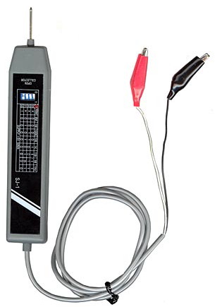
If I find questionable IC behavior I sometime use an old but useful
tool. It is a logic signal injector. The device can override almost any logic
input, even if it is connected to some other logic device. It can pulse a
normally logic low state and make it high briefly. By pulsing the input and
looking at the output, you can quickly determine if the part is working. Also,
some outputs in a circuit should have certain waveforms or logic conditions. A
binary counter as an example will have outputs with known signals. An output
which is supposed to have a 1MHz square wave but shows a fixed logic state will be a
clue of a problem within the part.
Another trick I sometimes use in
tracking down power supply problems is to switch my multimeter to the 200mv DC scale
and start looking at voltage drops. I place the positive meter probe on the
+5v output directly at the voltage regulator. I then use the negative probe to
look at the voltage I see at the +5v supply connections going to the various parts.
The small copper traces on the circuit board have enough resistance that I can
quickly determine which way the current was flowing. If parts clear on the
other side of the board have the highest voltage drop, then that tells me that
something was drawing heavy current on that side.
On the other hand, if I see
little voltage at many nearby parts, then I most likely can eliminate them.
But, this method only works when there is current flowing through the supply lines.
If there is a direct short on the supply to ground some place, then the voltage
regulator will shut down, disrupting the current. Under these conditions, you
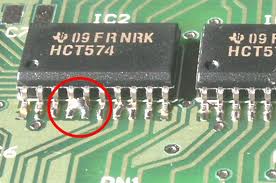
may have to resort to cutting some key +5v traces on the board to try and isolate
where the short is located. The short may be a solder bridge as shown below. |
 |
|
Logic Pulser |
|
|
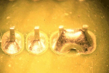
I have also fixed boards where I found a solder flake which got lodged
under an IC, shorting out some pins. Ever since manufacturers have switched to lead
free solder there has been a rash of problems caused by tin whiskers. These are
microscopic tin hairs which can grow between pins on a circuit board. They are often
so small that it does take some magnification to see them. Boards covered with
plastic conformal coating usually don’t have tin problems. |
 |
 |
 |
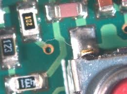 |
| solder bridge |
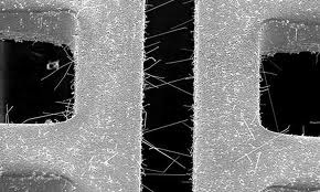
tin whiskers |
|
|
A good circuit design will scatter many noise filtering capacitors across
the +5v supply over the entire circuit board. On high speed circuits, a 0.1uF
“decoupling” cap is often assigned to each logic part. Tantalum electrolytic caps
are also used to help absorb some noise caused by high current spikes on the +5v supply.
Tantalum caps are especially prone to failure and often fail as a short circuit.
Ceramic caps fail less often but they have been known to short out. I look for any
discolored parts. A part may often start dying by first drawing excessive current,
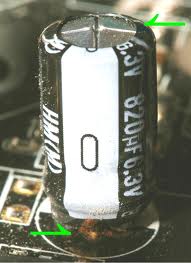
heating up the part, before it finally forms a short. Many aluminum electrolytic
capacitors exhibit a failure by spitting out liquid electrolyte onto the board. A
quick scan around the board may pinpoint the problem. Any discolored parts should be
replaced. |
 |
 |
 |
 |
|
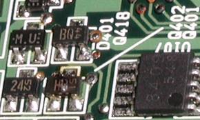
Burned Resistor |
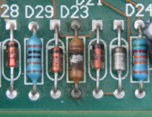
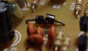
Burned Diode |
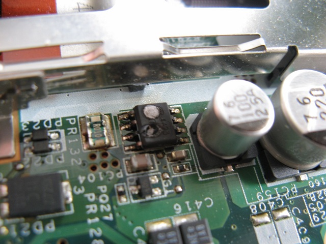
Burnt IC |
Discolored Capacitor |
|
|
If the board is new, fresh off the production line, I switch to a visual
inspection mode. I first look for solder shorts. These are the most common
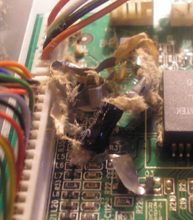
problem. Backwards electrolytic capacitors will usually fail right away, often in a
spectacular explosion of smoke and sparks. Backwards diodes and transistors too will
often pop open. |
 |
 |
|
Exploded Capacitor |
Burned Transistor |
|
|
You can sometimes spot a problem by comparing a failed board with a known
good one. A reversed IC, a backwards diode or capacitor or solder bridge between two
pads are often spotted this way. |
|
Not very often, but I sometimes I do have to lift parts, cut traces and
snip leads to help track down a problem. Many years ago, after hours of searching, I
finally discovered the cause for the failure of a circuit board used in an oscilloscope.
The circuit board had 2 inner printed layers (4 layer board) and somewhere inside the
circuit board, two solder pads had a short between them. There was no way to fix the
problem, so the whole board had to be scraped. Finally, when all else fails, I may
have to use a “shotgun” approach and start replacing parts whose failure could explain the
symptoms. I once fixed a board which had been hit with a big static discharge.
The discharge killed a dozen parts. One by one, I had to replace each part until the
board was functional again. |
|
In the end, my power supply problem was a bad logic IC.
It might have been zapped by static or maybe a solder flake fell across its leads long
enough to burn up the part, then that same flake fell away, leaving no clue. I just
pulled out the old part and slapped in a new one. When troubleshooting and repairing
I always make sure I have on my anti-static bracelet. It is connected to good earth
ground. Static can easily kill many parts. |
 |
How do
I replace an IC? In both through-hole and surface mounted cases, I like to
clip the leads away from the body of the part first, leaving only the leads left
soldered onto the board. I then use my soldering iron and tweezers and pluck
the leads off the board one by one. Once all the leads have been removed, I
clean up the pads and holes with a solder sucker or solder wick and then solder in a
new part. I use a “no clean” solder, which leaves very little residue. If the
board is especially dirty, I use a combination of soap, water and rubbing alcohol
with a final rinse in distilled water.
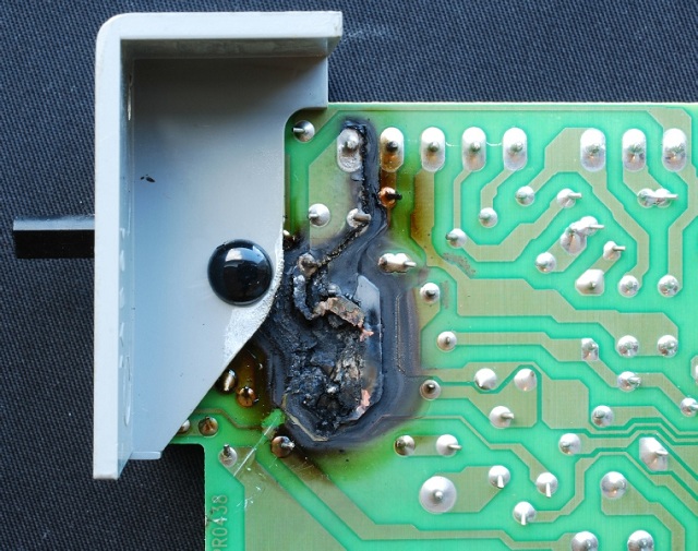
Sometimes, when a board has
suffered a catastrophic component failure, so much damage has been done to the board
that a black char is left on the board. I don’t bother with those boards.
The char is often partly conductive and almost impossible to clean. |
|
Burned PC Board |
|
|
|
|