Testing
LED Light Intensity
By: Dave Johnson |
 |
|
 |
The human eye is not a good
instrument for measuring how bright a light is. Our eyes tend to be
logarithmic. When making a comparison between two lights, unless one
light is considerably brighter than the other, you will not know which is
really brighter. You need a linear device to make such a
measurement. You don’t have to
spend a lot of money to make good intensity measurements. A fairly
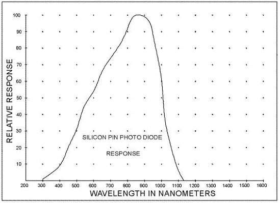
accurate device is the bare silicon photodiode. As the cart below
illustrates, a silicon photodiode has a broad light response, covering
invisible ultraviolet, through the entire visible spectrum, into the
invisible near infrared band. These parts act as small solar cells.
The DC current generated by them is directly proportional to the
|
| light
intensity. By positioning one of these things directly in front of a
light source, you can accurately measure how bright one part is with
respect to another. This method does not take into account the
emission pattern of the part, or its color. It only tells you what
the relative intensity is. It works best when you are comparing one
device with another of the same color, package size and emission pattern.
By placing the photodiode very close to the LED under test, the emission
pattern has less impact on the intensity reading. Most of the light
emitted, strikes the photodiode. |
|
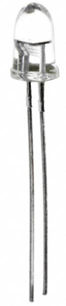
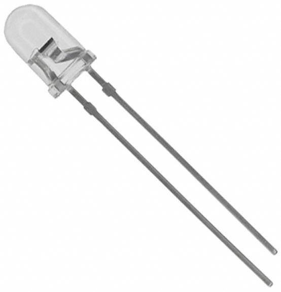
| The most popular LED package
is the 5mm diameter T 1 ľ part. The position of the LED chip within
the epoxy package controls the light pattern that emerges. If the
chip is mounted back from the lens, the pattern is narrow.
Conversely, if the chip is moved closer to the lens, the pattern is
broader. The standard LED specification for the emission angle is
the angle from the center of the part to the half power point. This
is a half angle. Some LED data
sheets double this angle for a full angle. So, a device with a 10
degree half angle may be listed as having an emission pattern of 20
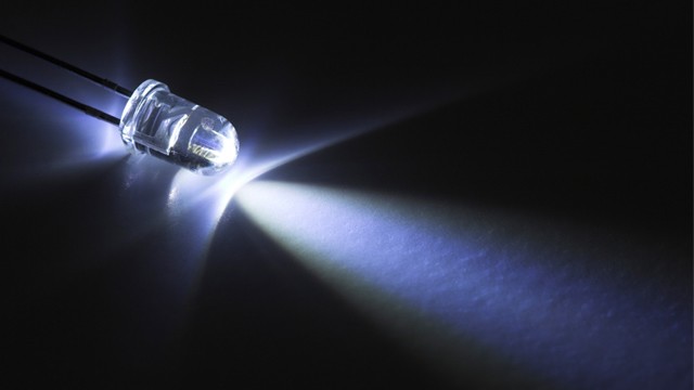
degrees. Keep in mind that when viewed from some distance away, a
LED with a narrow emission pattern will appear brighter than one with a
broader pattern, even if the broader pattern part emits more light power. |
 |
|
 |
 |
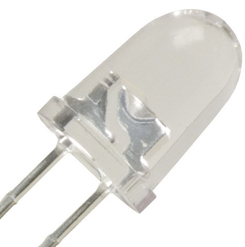
| LED with a
Narrow Pattern |
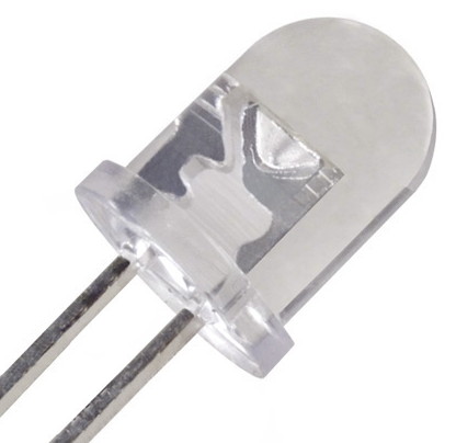
LED with a
Broad Pattern |
|
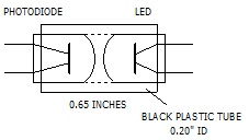
| When testing T 1 ľ
type LEDs, I reach for my photodiode test tool. As illustrated, this
assembly is just a photodiode slipped into a black plastic tube about 0.65
inches long. The LED under test slides into the other end of the tube.
The black plastic prevents most ambient light from reaching the photodiode.
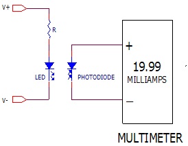
I then connect the photodiode to my multimeter, set for the DC current mode and
a 20ma range. The current reading I get on the multimeter is then the
light intensity. |
 |
 |
|
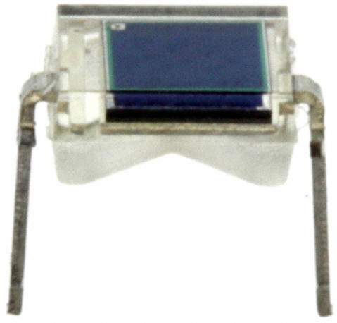
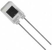
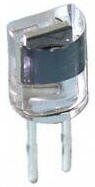
The photodiode I use most
often use is the PDB-C142 from Advanced Photonix Inc. This device
costs about $3.00 and is available from
www.digikey.com. Other possible devices are shown below.
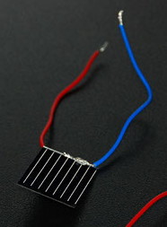
In a pinch, you can even use a small solar cell. When using a bare
solar cell try to make your measurements under low ambient light levels.
Otherwise you will get a false reading. When picking a photodiode,
be sure to only use those with a clear window. Don’t use photodiodes
with a purple tint. These contain a special daylight blocking filter
which filters out most visible light. Also, be sure to only use a
photodiode. Phototransistors are often listed as light detectors but
they are very logarithmic parts and will not give you a good linear
response. |
|
 |
 |
 |
 |
 |
| Advanced
Photonix PDB-C142 |
BPW34
|
BPW46 |
PDVC158 |
BPV10 |
|
 |
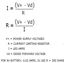
When testing LEDs, the best
way to drive them is with a constant current. Twenty milliamps seems
to be the industry standard for most LEDs. You can approximate a
constant current by inserting a resistor in series with the LED and a DC
power supply. You can use the formula below for picking the resistor
value. Red LEDs have a forward voltage between 1.5v and 2.0v.
Orange and yellow require about 2 volts. Green parts need about 2.5v
to 2.8v. Blue and white LEDs need something between 3.2v and 3.6v.
Nearly all ultraviolet LEDs need about 3.6v while nearly all infrared LEDs
need about 1.5v. |
 |
| Small Solar
Cell |
|
| Over the years I have
been very disappointed by how poor some white LEDs used in many solar path
lights and flash lights are. They may look bright but by using this simple
test tool, the intensity measurements tell a different story. Some white
LEDs made by Cree are two and sometimes three times brighter at the same current
level. If you are not satisfied with a particular path light’s output, you
can make a big difference just by replacing the LED with a better part from
Cree. Also, if you are satisfied with the path light’s intensity but not
the time it operates, you can replace the light’s LED with a Cree part and
extend the operating time by 2X or 3X by increasing the internal resistor which
controls the LED current and thus lowering the drive current. Flashlights
too can benefit by swapping out the LEDs for better parts. I have also
used this simple setup to monitor how some parts age over time. Some cheap
white LEDs offered on eBay fade to a half intensity level in just a few weeks of
use. |
|
|