Low Power AM Transmitter
By: Dave JohnsonA while
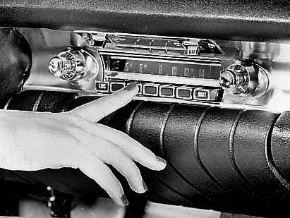
back, I got an email from someone who drove around in a restored 1960s car. He
wanted to be able to leave the old car’s original AM radio intact but he wanted to
play music from his Ipod MP3 player through the car’s radio. In other words, he
wanted a |
 |
|
radio adapter, similar to those
often used in cars today, which send the audio information to a car’s FM radio. But
he wanted to transmit the information on AM instead. I didn’t have a ready solution
for this at the time but I’ve been thinking about it. I thought it would be an
interesting project. |
|
|
There are a lot of AM radio transmitter circuits posted on the Internet. Many
use a few transistors as audio Amps and oscillators and are designed as low
power AM transmitters, feeding a wire antenna. The audio signal feeds some of
the transistor bias circuits, causing the Amplitude of the RF signal to be
modulated. But, for this application, only a very short range is needed. I
might try and come up with my own design. I think the antenna for this thing
would require some careful thought and perhaps some experiments. The
transmitter does not need much power, since the distance between the
transmitter and the car’s AM radio receiver would only be a few feet. Still,
some experiments would be necessary to see just how much transmitter power
would be needed and what type of antenna works the best. I would like to keep
the overall transmitter package compact. Maybe a ferrite rod antenna could be
used so there would be no a need for any antenna wire. I could also tap into
the car’s 12v power though the cigarette lighter. That way I would not have
to worry about a battery pack. After some experiments perhaps I could then
decide if the transmitter could be battery powered. |
|
AM radio
from the 1960’s |
|
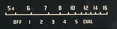 |
The US AM radio band ranges from about 540KHz to 1.6MHz. Many
AM dials also dip down to about 530KHz. The low frequencies might be a good
target since few radio stations transmit at that end. However, 530KHz is
often used for road condition alerts and weather reports. Every region of the
country will have different clear AM channels, so perhaps some transmitter
frequency adjustment or selection will be needed. |
|
AM Radio
Dial |
|
|
The best way to insure a rock solid transmitter frequency is to use a
quartz crystal. However, a quick review of what crystal frequencies are available
from the Digikey catalog was disappointing. One 4.43MHz crystal, when divided down
by 8, would yield a frequency of 553KHz. That might work. Also, ceramic
resonators, although not as accurate as a crystal, are available in 540KHz, 640KHz,
800KHz, 1MHz and 1.22MHz frequencies. A selector switch could be used to pick one
of those. I also could use an LC oscillator and vary either the capacitor or the
inductor to change the frequency. This is a bit less desirable, since one would not
know what frequency was “dialed in” unless the adjustment dial could be calibrated.
Or you could tune the car’s AM radio to a clear channel first, and then adjust the
transmitter frequency to match. That would work. Unless the car is being driven
across country, once the transmitter frequency was set, it should be OK from then
on. |
|
A RC type oscillator could be configured to run at the right
frequency but it would tend to drift due to temperature and supply voltage changes.
A more stable RC oscillator might use the LTC1799 from Linear Technology. This
device’s frequency can be set with a single resistor and would be much more stable
with temperature. A carefully designed circuit could allow a multi-turn pot to
adjust the radio transmitter frequency over a narrow range. In fact, it might be
possible to use fixed resistor values to select the desired frequency. A chart
could be made which showed the relationship between the resistor value and the
transmitter frequency. Resistors with a 1% accuracy are pretty common. |
|
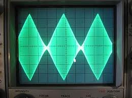
The conventional way to produce an Amplitude modulated RF signal is
shown below. A RF oscillator’s Amplitude is varied by a DC voltage, corresponding
to the audio information. This is the classic “amplitude modulation” method. The
signal emerging from the circuit is usually connected to a LC tank circuit, to
filter out the harmonics and provide a better impedance match to an antenna. If I
want to keep the range of an AM radio transmitter short, I should try to restrict
the size of the antenna. A pure magnetic field transmitter should work, using a
coil of wire as the antenna. |
|
|
|
A variation of the classic oscillator modulation method is shown
below. It varies the Amplitude of a square wave RF signal generator. Its output
would then drive a series resonant LC network with a medium Q value. The square
wave drive would be turned into a nice sine wave transmitter signal. The inductor
of the LC network would send magnetic information to the car’s radio. In addition,
a short piece of wire would provide the electric field connection. I like this idea
but again, it would take some experimentation to see what kind of coil would work
best. |
|
|
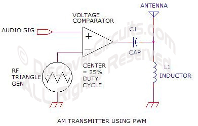 |
Another way
to produce the Amplitude modulated signal would be to use a pulse width
modulation (PWM) scheme as shown below. This method is often used in “class
D” audio power Amps and allows for a very efficient driver. It might be an
interesting experiment to try the PWM technique. Instead of varying the drive
voltage with audio information, the pulse width of the RF drive signal would
be modulated. The PWM signal would be set for a duty cycle of about 25%. The
audio signal would then increase and decrease the pulse width of the RF. The
Amplitude would be maximized at a 50% duty cycle and would be much less, as
the duty cycle (pulse width) became shorter. Again, a series resonant LC tank
circuit would smooth out the signal into a clean sine wave whose Amplitude
would vary with the audio signal. Although this type of circuit would be more
complex, it would be more efficient than the classic AM method. |
|
|
To send the information from the transmitter box to the car’s radio,
some kind of antenna would be needed. I would like to try a pure magnetic method to
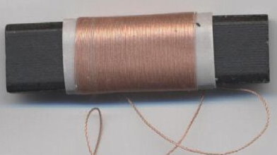
bridge that distance. Inside nearly every AM radio receiver is a ferrite
“loopstick” antenna as shown below. This type of device might make a nice antenna
for the transmitter as well. It is a bit directional and would need to be oriented
properly to the car’s own antenna to work but it would keep the system compact. If
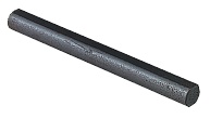
necessary, a better antenna might use a larger ferrite rod. These are available in
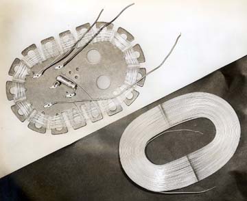
lengths out to about 10 inches. Another option would be a large coil loop as shown
below. This would certainly work but would be fairly large. |
 |
 |
 |
|
AM Radio Loop Stick Antenna |
AM Radio Coil Antenna |
Ferrite Rod |
|
|
I think the first order of business would be to connect my signal
generator, set at 530KHz, to a push-pull type driver circuit similar to the circuit
below. I can chop the RF at a 50% duty cycle at say 400Hz, to produce an AM signal. |
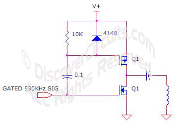 |
| Push-Pull Driver |
|
|
I would then measure the inductance of an off-the-shelf loop stick
antenna coil and find a suitable capacitor, so the LC network will resonant at
530KHz. I will then see if that circuit can transmit enough RF signal to the car’s
AM radio. I can vary the driver’s supply voltage, to control the power to the
antenna. This will give me an idea if a small loop stick coil will work. It those
results are disappointing, I can move up to a larger ferrite rod or maybe even an
open air coil. I will let you know what I discover. |
|
LTC1799 Data Sheet |