|
The control board
was housed in a water tight plastic box, which in turn was housed inside a metal
enclosure. The company said the symptoms were fairly consistent. Often the
valves did not fully open or close. But, every time they tested the suspect
circuit boards at their facility, they worked perfectly. |
|
I asked them to send me a few boards to test, a couple motor/valve
assemblies and any supporting documentation. A shortened motor pulse time
would explain why the units were not fully closing or opening the valve. I
suspected there was a temperature issue. The metal housing might protect the
electronics from rain and snow but did nothing about the large temperature swings
which can occur in an outside environment. |
|
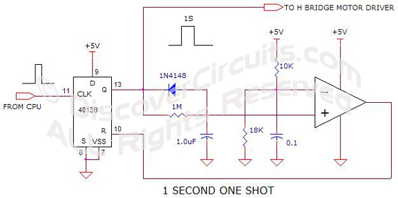
I looked at the circuit schematic. As shown below, the company
used a pretty simple one-shot circuit. The circuit used a flip/flop and an op
Amp, to produce an accurate 1 second pulse. The 1M resistor and the 1uF
capacitor formed the (RC) timing components, which defined the duration of the motor
operation. A short pulse from their main computer at the input of the circuit fired
the one shot. The pulse was supposed to be long enough to fully open or close
the valve but not so long that the motor was being driven in a stalled state for
very long. At first glance, all seemed to be in order. I fired up one of the
circuit boards and connected one of their motor/valve assemblies. At my test
bench, the motor and valve seemed to work perfectly and the pulse measured close to
1 second. Using a hair dryer and some Freon freeze spray, I was able to heat
and cool the whole board. Bingo! In both hot and cold conditions, the
valve did not fully open or close. One or more of the components on the board
were quite temperature sensitive. |
|
|
|
Looking at the schematic, the 1uF capacitor was most likely the part
which was temperature sensitive. Resistors are fairly stable and the op Amp should
be rock solid. With the freeze spray and a soldering iron, I could prove that the
capacitor was indeed the root cause for the shortened power pulse to the motor.
Now, how do I fix the problem? |
 |
|
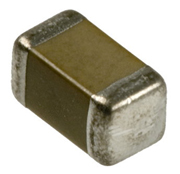
1uF 0805 Ceramic Capacitor |
|
I
shifted my focus to the assembly material list. The part called out was a 1uF
16v 0805 surface mounted ceramic capacitor with a 5% tolerance. But, they
didn’t specify the kind of ceramic capacitor. When I looked up the specified
part number, I noticed that the part was indeed a 1uF capacitor but had a Y5V
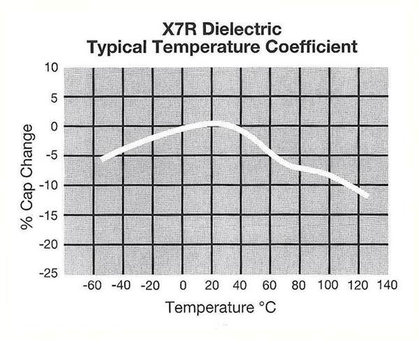
dielectric. Digging a little deeper, I saw that the Y5V dielectric had a
terrible temperature coefficient as shown below.
The inverted V shape of the
curve meant that the capacitance would decrease when the part was either hot or
cold. This now all made sense. At room temperature, the whole circuit
worked perfectly. But, when the assembly was quite cold or hot, the motor
pulse would be considerably shorter. At the extreme temperature ranges, the
pulse could be only half as long as it should be. |
|
|
|
The fix was to specify a more stable capacitor. As shown below,
a similar part, using a X7R dielectric would only change by about 7% when hot. |
|
|
|
So, the solution was to specify a X7R part. Those boards
containing the wrong capacitor could be easily fixed by replacing the timing
capacitor. Once all the changes were made, the company reported to me that
they had no more problems. |