HOME Schematics Hobby Corner Dave's Circuits Electronic Resources Book Corner Contact Info


Wily Widget

  Previous Issues

Coin Operated Telescope

It was almost lunch time when Wily got a call from San Francisco.  A company there had been building and selling coin operated telescopes for many years.  Hundreds were used around the city and several hundred more were used elsewhere.  Wily listened as the caller described their telescope.  The company had been using a mechanical system to accept coins and activate the telescope’s clock mechanism.  The act of inserting a quarter into the slot and turning the dial opened an eyepiece shutter and started a clock.  Once the clock timed out, the shutter would snap close again.  Their telescope used a mechanism very similar to those used in city parking meters.  This system served them well but the company felt it was time to switch to an electronic system.  Over the years, the cost of the mechanical system kept getting higher and higher.  They thought that by going to an electronic system, they could bring the cost down and perhaps increase reliability.  Their pure mechanical system did suffer from corrosion from the salt air.

Their first attempt at an electronic system was not very successful.  That system used a power hungry circuit using a solenoid, powered by a large sealed battery.  The battery had to be replaced every few months. Could Wily come up with a better system?

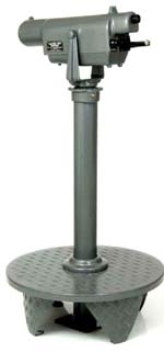
Wily asked some more questions about their system.  Their telescope had a simple single lens.  In their electronic prototype, they used a solenoid to hold open a spring loaded “flapper door” shutter, which opened and closed a light path in the eyepiece.  The solenoid was the major power drain from the battery.  They were very pleased with the new coin acceptance mechanism they switched to in the prototype and wanted to stay with it.  The system was very foolproof and had few mechanical parts.  It accepted only quarters. Other coins dropped through.  A simple switch closure occurred, when a quarter fell into the coin box.
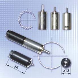
Wily gave some thought to this system and decided that he could solve the power problem with a tiny gear motor to move the flapper shutter.  He gave the company a rough estimate for the cost of a working prototype of the timer electronics and the motor control.  They agreed on the price and sent Wily some money to cinch the deal.

The company felt they could handle the shutter mechanical design.  That allowed Wily to concentrate on the electronics.  The simple machine operation was defined.  Once the coin was accepted and fell into the coin box, a motor would open the shutter for 2 minutes.  After those minutes had elapsed, the motor would reverse direction and close the shutter.  The timer would allow only one coin at a time.   

The first thing Wily had to do was select the gear motor.  He loved the motors from Micromo and had much success with their parts.  These are tiny yet powerful motors that required surprisingly little power.  Wily selected a 6v motor with a 1024:1 gear ratio.  The complete motor assembly was no bigger than Wily’s little finger.  When powered by a 9v battery the motor required only 8ma of current and produced a 10 RPM shaft speed with lots of torque.

The plan was to connect the optical flapper door shutter directly to the motor shaft.  The motor only had to move the shaft through ¼ of a full rotation or 90 degrees to open and close the shutter.  This motion required only 1.5 seconds to move the 90 degrees, when powered from a 9v DC source.  Based on the statistics from the telescope company, this meant that a single standard 9v battery could be used to power the whole system for more than a year.  Wily figured that he would recommend that his client replace the battery once each year.

The electronic timing sequence was fairly simple.  The coin acceptance mechanism would provide a switch closure when a quarter fell into the coin box.  This would start a timer.  Power would be routed to the flapper motor.  When the flapper was fully open, a motor stall current sensor would turn off power to the motor, leaving the shutter in the fully open position.  When the timer timed out, the polarity of the motor drive would be reverses.  When the shutter flapper was in the fully closed position, the motor would again stall, which would turn off power to the motor.  Instead of a microprocessor, Wily designed the control system using some standard logic devices.  Click here for this circuit.

http://www.micromo.com/ miniature gear motors


February 2010       Issue 6

Page 1 Back
Envelope
Circuit
Diagnosis
Experimenter's
Corner
Good Idea
gone Badly
New Products Rants &
Raves
What the World
needs Now
Wily Widget


Imagineering Ezine    Discover Solar Energy Dave Johnson & Associates Faraday Touch Switches


 About Us   |  Advertise on DiscoverCircuits.com   |   Report Broken Links  |    Link to DiscoverCircuits.com  |   
Privacy Policy


Discovercircuits.com endeavors to credit original designers.   Please alert us by eMail so we can
delete links to material that have been copied without your permission
.   Thank you.


© Copyright of all original material on this website is the property
of David A. Johnson, P.E. (Dave Johnson & Associates ) unless otherwise noted.  

Linking is ALLOWED but COPYING any content or graphics to your web site is EXPRESSLY PROHIBITED.
All material is provided "as is" without guarantees or warranty of any kind, either expressed or implied.