|
During initial oscilloscope production, we discovered some erratic
operation in some of the vertical Amplifier channels. The symptoms were not
consistent but they always seemed to effect the Amplitude calibration of the vertical
Amps. Sometimes the DC offset was way too high. Other times the Amplifier gain was
way too low, indicating that the signal was being attenuated. We could solve the
problem by swapping out one vertical Amp card for another, so we were pretty sure that the
defect was on the card. But, all too often, the card, which would not work in one
machine, would work fine in another. We were really scratching our heads on this
one. I decided to go back through the production line process and see if I could
spot something. Nothing seemed to be amiss. This new oscilloscope was being made in
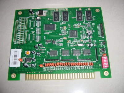
much the same way as other models, using the same procedures and materials. I did notice
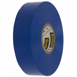
that a protective tape was being used to cover the gold edge contacts during the board
assembly and cleaning process and was only removed when the board was ready to be
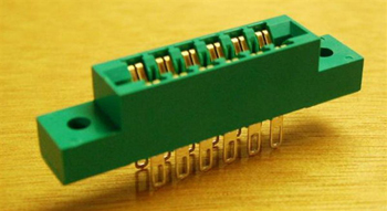
installed in the scope. Looking at the oscilloscope schematic I did notice that the
vertical Amplifier channels were routed through the connector and they did have a very
high impedance. After close inspection of the contacts under a microscope, I could
just make out some residue left by the adhesive used on the protective tape, covering the
contacts. The company had been using this stuff for years without any problem but
perhaps, just perhaps, this was the first time that such sensitive circuits were being
routed through the edge connectors. I took a board which exhibited problems and
carefully cleaned the edge contacts with an aggressive solvent, followed by a deionized
water rinse and a hot air dryer. |