|
Long Range Laser Communications
I got an email from a
hobbyist who wanted to know if a visible red laser pointer could somehow be used in
a long range free space communications link, specifically an optical Ethernet.
He really wanted to know the practical range of a system using a cheap visible red
laser pointer. Based on my experience in similar systems, I have a pretty good
idea how far it could go but let’s run some quick calculations and see what is
really possible. |
 |
|
|
| The
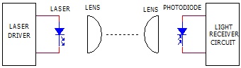
sketch below illustrates how a laser based communications link would work.
Light from a laser diode is routed through a lens, which shapes the light into a
tight beam. At the receiving end, another lens is used to collect some of that
light and focuses it onto a light detector. The laser is modulated in some way
to encode the information into bits of digital information. For our example,
let’s assume that the laser is modulated at a frequency between 10MHz and 50MHz. |
|
 |
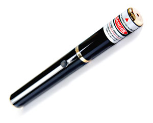
| A
typical laser pointer puts out about 5mw of laser light. Although it may be
possible to make these things put out more light, let’s use this figure. |
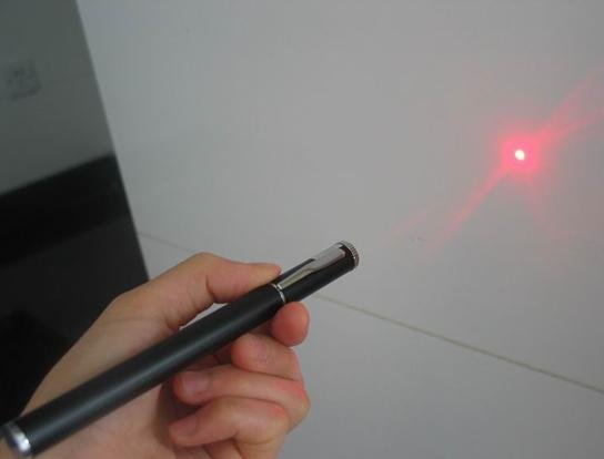
| The
divergence half angle of a laser pointer is a measure of how tight the beam remains
over some given distance. I measured the spot diameter of laser light from
several red laser pointers I had laying around. The diameters ranged from 1.5
inches to 3 inches at a distance of 200 feet. Some lasers may be tighter than
this figure and some will be wider but let’s use 3 inches as a spot size figure.
Some laser pointers use better optics than others, so the spot may be slightly
elliptical in shape while others are more round. If the laser pointer
manufacturer provides a divergence angle, it is usually given in milliradians.
A radian is 57 degrees, so a milliradian is 0.057 degrees. Often, a laser pointer
will claim a divergence angle less than one milliradian. |
 |
 |
|
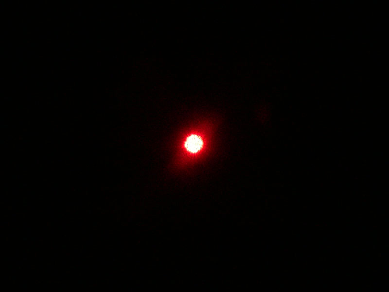
Laser Spot |
Laser Spot |
|
| Here
is the equation I use to define the behavior of the laser light as it travels over
some distance. The laser spot diameter, d, at some distance Y is: d = 2 x (tan
D) x Y, where D is the divergence half angle in degrees. Solving for D, I come
up with an angle of about 0.036 degrees for the laser with a 3 inch spot at 200
feet. |
|
Knowing the divergence angle allows you to predict how much light will strike a
distant target. Keep in mind that in nearly all cases the area of illumination
will be much larger than the light collection area, which actually directs the light
onto a detector. |
| From
my own experience in designing light receivers, I know that a good minimum light
power figure for a reasonable signal to noise ratio at this medium modulation
frequency is 100 nanowatts. At much lower frequencies, I have been able to
work with less than one nanowatt. But, let’s use 100 nanowatts as our minimum
signal level. |
| If we
start out with 0.005 watts from the laser and we need only 100 nanowatts at the
receiver to communicate, then the ratio of launched light to collected light can be
as large as 50,000:1. That means that the ratio of the illuminated area to
light receiver collection area can be as high as this same ratio. Knowing that
the area tracks a square function with respect to diameter, then the illuminated
diameter can be the square root of 50,000 or 223 times larger than the receiver lens
diameter. For this example, let’s use a receiver lens diameter of 2 inches.
That means that the illumination spot diameter can be up to 2 x 223 or 447 inches,
which is 37 feet. If we insert this figure into the equation above and solve
for Y we get a figure of 30,000 feet for a maximum range. Wow, that is 5.5 miles.
That is not bad for a cheap laser pointer. Of course, this calculation does
not count for some attenuation of the signal as it goes through the air. Also,
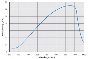
my 100nw minimum signal level was based on using infrared laser light. As the
drawing below shows, a 2:1 penalty is paid when using a visible red 630nm laser
light source instead of an infrared 900nm laser. The silicon based photodiode
light detector is much more sensitive to infrared light than visible light.
Still, it is a lot easier to align a visible light source than one which is
invisible to the human eye. Overall, I think a range of about 2 miles would be
a reasonable figure to expect when using a 5mw visible red laser pointer, with a 2
inch light receiver lens. |
 |
|
Typical Silicon Photo Diode Response |
| If
you want to go farther than 2 miles, there are many things that could be done.
Much more powerful laser diodes are available. I have a few 100mw red laser
diodes in my inventory, which can launch 20 times more light. Such an increase
in light level will mean a 4.5 times improvement in distance. Next, better
larger lenses can be used with the laser, to tighten up the laser beam. A
divergence angle of 0.003 degrees would certainly be possible. This change
would increase the maximum distance by another factor of X12. Finally, if a
larger lens were used at the receiver, say a 12 inch diameter Fresnel lens, the
distance could be extended by another factor of 6. If all of this was
done, then the distance could be some 650 miles. This kind of range is well
over the horizon even from a mountain top. So, in conclusion, a 5mw laser can
indeed be used for fairly long range optical communications. In the future, I
will be showing how to modulate a laser pointer and receive its light for high speed
optical communications, through the air. |
|