|

|
|
|
|
|
|
|
|
Vertically Lifting Security Gate Power
Source
Schematic |
|

|
Wily started to draw up a
circuit for this application. To insure a long life, he knew that he had to
carefully control the voltage across each capacitor. The 2.7v maximum voltage across
each capacitor should not be allowed to be exceeded. Since the solar panel voltage
could exceed 18v on a cold sunny day, he had to prevent overcharging the 13.5v bank.
Also, since the weakest capacitor in the bank would reach its 2.7v maximum voltage first,
he needed to come up with a way to shunt excess current around each device when that
voltage was reached. A shunt type regulator should work the best for this kind of
need. This method would help insure a “balanced” capacitor bank. |
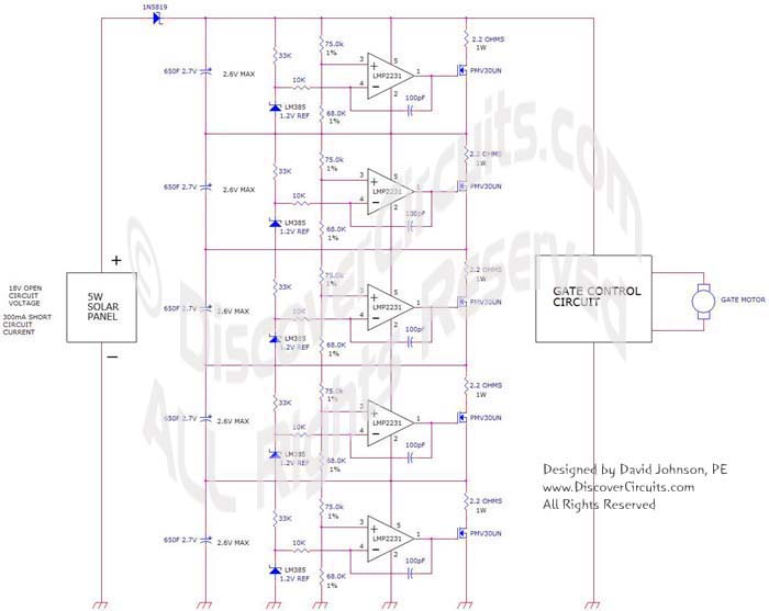
| The circuit that Wily came up
with is shown below. It uses 5 identical circuits. Each one is wired in
parallel with it assigned 650F super capacitor. A LM385 provides a 1.2v voltage
reference. A resistor divider measures the voltage across the capacitor and feeds
the voltage to a low power, low voltage op Amp. The output of the op Amp drives an
n-channel FET. Wily designed the circuit for a maximum charge current of 600ma.
This would allow the use of a 10 watt solar panel, if needed, in the future. Each of
the five circuits forms a shunt type voltage regulator, limiting the voltage across each
capacitor to about 2.6v. |
|
Wily was able to find the
Maxwell supercapacitors on Ebay for $30 each. With shipping, the total for the
capacitor bank was $160. Wily wired up the bank of caps and the 5 limiting networks
and shipped if off to his client. The client removed the lead acid battery and
connected up the super capacitor bank in its place. Wily recommended that the
capacitor voltage be monitored on a sunny day and told his client not to try and use the
gate until the capacitor bank voltage was above 12v. Once fully charged, the unit
performed flawlessly. The high quality capacitor bank should last for at least 10
years. |
|
 |
|
Click on above schematic to view PDF version |
|
|
|