|

|
|
|
|
|
|
|
|
Vertically Lifting Security Gate Power
Source |
 |
Wily got a call from one of his
old clients. A few years earlier Wily had designed a control circuit for the
client’s nifty security gate, which lifted vertically, instead of the usual horizontal
motion. The act of moving the gate vertically and folding up was ideal for mountain
homes, where narrow roads and heavy snow depths were common. His old client had a
request from one of his customers who wanted a gate power source with a much longer life
than the usual 3 to 5 years that a lead acid battery offered. The customer said that he
had batteries die at some very inconvenient times. Could Wily come up with
something? |
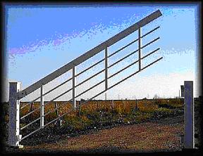
| The vertical lifting security
gates, as shown below, were most often installed far from any AC power source. The
standard system used a small 5 watt solar panel and a 12v sealed lead acid battery as a
power source. Both the battery and the control circuit board were housed inside an
insulated plastic case. A weather protected keypad on both sides of the gate allowed
gate operation without getting out of the vehicle. Standard wireless garage door opener
“clicker” remotes were also used. Wily asked his old client some questions, mostly to
refresh his memory about the gate system and to get information from his client’s
customer. Wily especially wanted to how often the gate was typically used each day.
Wily told his client that he thought he had a solution as long as the customer was
willing to spend some money on a better energy storage device. |
|
|
| The
security gate was moved up and down using a 12v brush type DC motor, connected to a
quality worm gear. The motor drew about 5 Amps for 10 seconds, to raise or lower the
gate. Limit switches and the circuit board controlled the end of travel motion of the
gate. The motor would work, even when the battery voltage was down to 8v, but would run
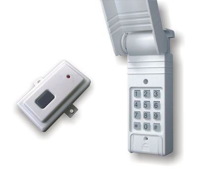
slower, taking perhaps 20 seconds to operate. The RF keypads were a wireless type and
contained their own battery. The RF keypad receiver module, mounted on the control
board, demanded very low power. The control circuit itself had a very low standby current
demand. Overall, only the motor required energy to operate. Wily’s client said that
his customer used the gate infrequently; perhaps less than 4 complete up and down
operations per 24 hour period and was used mostly during normal business hours. Wily
figured that there could at least be two complete up and down cycles, during dark winter
night conditions. Any energy storage device would therefore have to provide at least
enough energy for 4 motor activations, lasting 10 seconds each. |
| If
Wily’s client’s customer wanted something other than a battery to store the needed
energy, Wily figured that the best available device would be a supercapacitor bank. These
new devices should last at least 10 or more years and could easily pump out the needed
peak power. Wily figured that he should plan to size the capacitor bank so it could
operate the gate motor four times, without help from the solar panel. The solar
panel would be able to quickly charge up the capacitor between gate activations during sun
lit days but much more slowly during cloudy days. |
| Even on
cloudy weather, a useful amount of power could be pumped into the supercapacitor. During
cloudy days, the available power from the 5 watt panel might only be about 5% of the full
sunlight level or about 0.25 watts. Assuming about 8 hours of daylight, that meant
about 2 watt-hours could be collected, even on a cloudy day. If the gate motor
needed 60 watts for four 10 second operations, then the total energy needed for a typical
day would only be 2400 watt-seconds, which would be 0.7 watt-hours. The solar panel
should therefore be able to pump enough power back into the supercapacitor to keep it
charged. |
| So, in
review, the gate would draw 5 Amps for 40 seconds from the super capacitor on a typical
day. Wily decided to round this figure off to 60 seconds, for a 50% energy margin.
Starting from a fully charged 12v capacitor bank, Wily figured that the voltage drop
should not exceed 3 volts. This would take the capacitor bank down from a high of
12v to about 9v. |
| Using
the equation: dv/dt = I/C Wily could calculate how big the capacitor should be.
If dv was 3 volts, dt was 60 seconds and I was 5 Amps, then C worked out to 100 farads.
Since most supercapacitors were rated at 2.5v, he would need to wire 5 capacitors in
series to achieve a 12.5v bank. Other supercapacitors had a 2.7v rating, so the voltage
could range from a high of 13.5v to a low of 10.5v. If the total capacitance had to be
100 farads then each device needed to be at least 500 farads. |
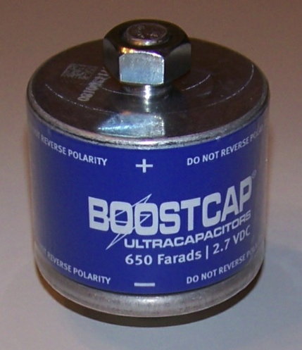
| Wily
knew of several supercapacitor manufacturers, but he especially liked the parts from
Maxwell. Maxwell sold a nice 650 farad 2.7v part, which should work fine for this
application. Five of them would yield a 13.5v 130 farad capacitor bank. Wily liked
the additional 30% storage this type of part would offer over his minimum 100 farad
requirement. |
 |
 |
 |
| Maxwell 650F
Supercapacitor |
RF Keypad and Clicker |
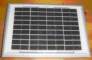
18v 5w Solar Panel |
|
|
Just to double check his
figures, Wily imagined how the gate might be used. Starting with a fully charged
capacitor bank, Wily imagined the home owner coming back from work at night, in total
darkness. The gate would be opened and then closed, drawing power from the
supercapactor. Then, early in the next morning, still in darkness, the gate would be
opened and closed again. These 4 motor cycles will cause the capacitor voltage to
drop from 13.5v to 12v. Even if the gate needed to be operated two one more times, then
there would still be enough energy stored to do it. During 8 full hours of cloudy weather
the solar panel should be able to fully charge the capacitor bank. |
|
Wily thought he better double
check this assumption. The 5 watt solar panel should be able to crank out about
300ma of current during clear sunlit days. During very cloudy days, the charge
current might drop to only 5% of that figure or about 15ma. Wily used the same dv/dt
= I/C equation to double check his figures. dt would be 8 hours or 29,000 seconds, I
would be 0.015 Amps and C would be 130 farads. Therefore, dv would be 3.3 volts.
Good, that meant that even with a much smaller current from the solar panel during cloudy
weather, the capacitor should still get charged. When the sun came out, the solar
panel current would jump up to 0.3 Amps again. Then to pump 3 volts back into the
capacitor, would only take 22 minutes. Wily felt pretty good with these figures.
It was always a compromise between having enough stored energy and keeping the cost down.
If there were a string of very very cloudy days or the solar panel became covered in snow
for several days, then a dead capacitor still might happen but the system would be able
recover as soon as the sun came out. A 10 watt solar panel might also be used to
decrease the likelihood of a dead capacitor by increasing the available power during
cloudy weather. |
|
Schematic of
Vertically Lifting Security Gate Power Source |
|
Wily Widget
the Lone Inventor Gadget &
Gizmo |
|
|
|